Audi A6 Typ 4G: Battery, Checking
Test Sequence
Battery, Checking, Vehicles with Battery Monitoring Control Module J367 or Energy Management Control Module J644 and Data Bus On Board Diagnostic Interface J533
- In certain model series the following is responsible for monitoring the electrical system: Energy Management Control Module -J644- or Battery Monitoring Control Module -J367- in connection with the Data Bus On Board Diagnostic Interface -J533-; allocation. Refer to → Wiring diagrams, Troubleshooting & Component locations. The battery test for these vehicles is performed during "Guided Fault Finding".
- If the battery test is not possible with "Guided Fault Finding" due to a partially or exhaustively discharged battery, the battery can be quickly evaluated with the help of the "battery test via current draw".
- Maintenance-free batteries must not be opened. Otherwise, the warranty is voided.
 Caution
It is not possible to check the battery using "Guided Fault Finding" through MY 2010 during the following procedure, even if the vehicle has a Battery Monitoring Control Module -J367-:
- A3 from MY 2004 (8P)
- TT from MY 2007 (8J)
- R8 from My 2007 (42)
Battery test. Refer to → Chapter "Checking the Battery - Vehicles without a Battery Monitoring Control Module -J367- or Energy Management Control Module -J644-".
 WARNING
Risk of injury. Follow all warning messages and safety precautions. Refer to → Chapter "Warnings and Safety Precautions".
Perform Tests in the Following Sequence:
1. Visual inspection. Refer to → Chapter "Visual Inspection".
2. Check the visual indicator color display (if equipped). Refer to → Chapter "Visual Indicator Color Display, Checking".
WARNING
Do not check or charge a Battery -A- when the visual indicator has "no color or is bright yellow". Jump starting must not be used!
There is a risk of explosion during testing, charging or jump starting.
These Batteries -A- must be replaced.
3. Battery Test with Vehicle Diagnostic Tester refer to → Chapter "Battery Test with Vehicle Diagnostic Tester".
Checking the Battery - Vehicles without a Battery Monitoring Control Module -J367- or Energy Management Control Module -J644-
Caution
It is not possible to check the battery using "Guided Fault Finding" through MY 2010 during the following procedure, even if the vehicle has a Battery Monitoring Control Module -J367-:
- A3 from MY 2004 (8P)
- TT from MY 2007 (8J)
- R8 from My 2007 (42)
WARNING
Risk of injury. Follow all warning messages and safety precautions. Refer to → Chapter "Warnings and Safety Precautions".
Perform the Tests in the Following Sequence:
1. Visual inspection. Refer to → Chapter "Visual Inspection".
2. Check the visual indicator color display (if equipped). Refer to → Chapter "Visual Indicator Color Display, Checking".
WARNING
Do not check or charge a Battery -A- when the visual indicator has "no color or is bright yellow". Jump starting must not be used!
There is a risk of explosion during testing, charging or jump starting.
These Batteries -A- must be replaced.
 Note
Note
The Battery Tester with Printer -VAS5097A- will no longer be used for warranty testing. Only the Battery Tester -VAS6161- is still being used.
3. Battery test with:
- Battery Tester -VAS6161-. Refer to → Chapter "Battery Tester -VAS6161-".
- Battery Tester with Printer -VAS5097A-. Refer to → Chapter "Battery Tester with Printer -VAS5097A-".
4. Depending on the result of the battery load test, "perform current draw test". Refer to → Chapter "Current Draw Test".
Visual Inspection
WARNING
Risk of injury. Follow all warning messages and safety precautions. Refer to → Chapter "Warnings and Safety Precautions".
Before any extensive measurements are taken, visually inspect the exterior of the battery, the connections, and the secure installation of the Battery -A-.
Caution
- An improperly secured Battery -A- can lead to damage.
- Excessive vibration due to an improperly secured battery will reduce the battery service life, and the battery hold-down bracket could damage the battery housing and lead to electrolyte leakage.
- Make sure the Battery -A- is secure. Tighten the mounting bolt to the tightening specification, if necessary.
- Visual Inspection Points
- Damage to the battery case. Acid can leak out if the case is damaged. Battery acid that has leaked out can cause severe damage to the vehicle. Acid that has leaked onto any part of the vehicle should be immediately treated with acid neutralizer or soap solution.
- Damage on the battery posts. If the battery terminals are damaged, contact with battery terminals clamps cannot be guaranteed. When connecting the battery terminal clamps, always keep the tightening specification for the corresponding vehicle from the repair manual in mind. Refer to → Electrical Equipment; Rep. Gr.27; Battery. If the battery post clamps are not correctly installed and secured, the wiring may burn. Substantial malfunctions to the electrical system are a consequence. Safe operation of the vehicle can no longer be guaranteed.
Visual Indicator Color Display, Checking
3-Color Visual Indicator, Checking, through 03/2008
WARNING
Risk of injury. Follow all warning messages and safety precautions. Refer to → Chapter "Warnings and Safety Precautions".
Visual Indicator General Information:
The visual indicator provides information concerning the electrolyte level and the Battery -A- charge level.
To obtain an accurate reading, gently tap the charge indicator with a screwdriver handle or rock vehicle slightly. By doing this, the air bubbles that occur normally during battery charging (even during vehicle operation) that adversely affect charge indicator reading will be displaced. Thereby, the color indicator of the visual indicator is more accurate.
Note
- Air bubbles can form under the visual indicator, especially if a Battery -A- was recharged or if the Battery -A- was charged while driving. These bubbles may cause the visual indicator to read inaccurately.
- As the charge indicator is located in a single cell, the indication is only valid for that cell. An exact assessment of battery condition should always be confirmed by performing battery test. Refer to → Chapter "Battery Load Test".
- The visual indicator can be installed at various locations on top of the Battery -A-.
There Are Three Possible Color Indications
- "Green": the Battery -A- is sufficiently charged.
- "Black": the Battery -A- is partially charged, the charge level is less than 65% or discharged.
- "No color/bright yellow": the Battery -A- must be replaced.
WARNING
Do not check or charge a Battery -A- when the visual indicator has "no color or is bright yellow". Jump starting must not be used!
There is a risk of explosion during testing, charging or jump starting.
These Batteries -A- must be replaced.
2-Color Visual Indicator, Checking, from 04/2008
WARNING
Risk of injury. Follow all warning messages and safety precautions. Refer to → Chapter "Warnings and Safety Precautions".
Visual Indicator General Information
The "green" visual indicator for the charge level indicator is no longer used for these Batteries -A-. Only "black" or "no color or bright yellow" are used.
The visual indicator shows the Battery -A- electrolyte level.
It is no longer possible to read the Battery -A- charge level using the visual indicator. It is necessary to perform a battery test. Refer to → Chapter "Battery Load Test".
To obtain an accurate reading, gently tap the charge indicator with a screwdriver handle or rock vehicle slightly. By doing this, the air bubbles that occur normally during battery charging (even during vehicle operation) that adversely affect charge indicator reading will be displaced. Thereby, the color indicator of the visual indicator is more accurate.
Note
- Air bubbles can form under the visual indicator, especially if a Battery -A- was recharged or if the Battery -A- was charged while driving. These bubbles may cause the visual indicator to read inaccurately.
- As the charge indicator is located in a single cell, the indication is only valid for that cell. An exact assessment of battery condition should always be confirmed by performing battery test. Refer to → Chapter "Battery Load Test".
- The visual indicator can be installed at various locations on top of the Battery -A-.
Two Visual Indicators Are Possible
- "black": the electrolyte level is OK
- "No color or light yellow": electrolyte level too low. Replace the Battery -A-.
WARNING
Do not check or charge a Battery -A- when the visual indicator has "no color or is bright yellow". Jump starting must not be used!
There is a risk of explosion during testing, charging or jump starting.
These Batteries -A- must be replaced.
Battery Test with Vehicle Diagnostic Tester
The Battery -A- can also be checked using the Vehicle Diagnostic Tester when it is installed and without being connected to a battery charger.
Special tools and workshop equipment required
- Vehicle Diagnostic Tester
Test Prerequisites
- No battery charger connected
- Battery -A- is connected.
- Battery temperature at least +10 ºC (50 ºF).
Procedure
Vehicle Diagnostic Tester is attached.
- Select the Diagnostic mode and start the diagnostics.
- Select the tab Test Plan.
- Select Select Individual Tests and choose the following sequence.
- Body
- Electrical Equipment
- 27 - Starter, voltage supply
- Electrical Components
- A - Battery, Checking
The Vehicle Diagnostic Tester continues with the battery test from here on.
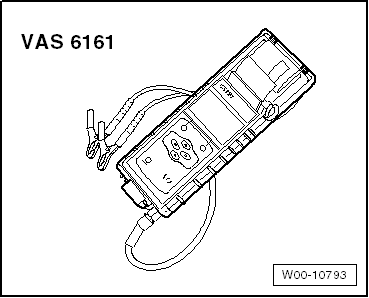
Battery Tester -VAS6161-
General Description:
WARNING
Risk of injury. Follow all warning messages and safety precautions. Refer to → Chapter "Warnings and Safety Precautions".
It is not necessary to disconnect or remove the Battery -A- when using the Battery Tester -VAS6161-.
The Battery Tester -VAS6161- does not load the Battery -A-. It is working according to the principle of dynamic conductivity.
The Battery Tester -VAS6161- stores all battery types.
The data can be stored on an SD memory card.
The Battery Tester -VAS6161- can be updated via an interface or a SD card, so that all battery data from Volkswagen is always current.
The integrated infrared sensor (measuring the battery temperature) increases the quality of the measurements.
As an option, there is a scanner available, which can be used to read the bar code on the Battery -A-.
Note
Observe the Battery Tester -VAS6161- Operating Instructions.
- Battery Tester -VAS6161- device description. Refer to → Chapter "Battery Tester -VAS6161- Device Description".
- Battery test. Refer to → Chapter "Battery Test, Performing using Battery Tester -VAS6161-".
- Maintenance test, performing. Refer to → Chapter "Maintenance Test, Performing".
- Service test, performing. Refer to → Chapter "Service Test, Performing".
- Warranty test, performing. Refer to → Chapter "Warranty Test, Performing".
- Printed test results explanations. Refer to → Chapter "Explanation of Test Results".
- Test result evaluation. Refer to → Chapter "Test Result Evaluation".
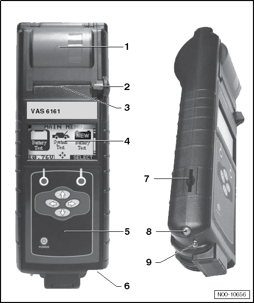
Battery Tester -VAS6161- Device Description
Battery Tester -VAS6161-
1 - Internal printer
2 - Operating lever for the paper tray
3 - Paper slot
4 - Main menu display
5 - Display with on/off-button
6 - Connection for the battery tester cable
7 - Slot for the SD memory card
8 - Infrared temperature sensor
9 - PC file transmitter
Battery Test, Performing using Battery Tester -VAS6161-
Special tools and workshop equipment required
- Battery Tester -VAS6161-
WARNING
Risk of injury. Follow all warning messages and safety precautions. Refer to → Chapter "Warnings and Safety Precautions".
Procedure
WARNING
Do not check or charge a Battery -A- when the visual indicator has "no color or is bright yellow". Jump starting must not be used!
There is a risk of explosion during testing, charging or jump starting.
These Batteries -A- must be replaced.
Note
The Battery -A- temperature must be at least 10 ºC (50 ºF).
- Turn off the ignition and all electrical consumers and remove the ignition key.
- Check the visual indicator on Batteries -A- with visual indicator. Refer to → Chapter "Battery, Checking, Vehicles with Battery Monitoring Control Module J367 or Energy Management Control Module J644 and Data Bus On Board Diagnostic Interface J533".
- Switch on the Battery Tester -VAS6161-. Refer to → Chapter "Battery Tester -VAS6161- Device Description".
- Connect the red terminal (+) to the positive terminal of the Battery -A-.
- Connect the black terminal (-) to the negative terminal for the Battery -A-.
Note
Make sure the test terminals make good contact!
- Select one of the following:
- Maintenance test (only on new vehicles before becoming inventory). Refer to → Chapter "Maintenance Test, Performing".
- Service test. Refer to → Chapter "Service Test, Performing".
- Warranty test. Refer to → Chapter "Warranty Test, Performing".
Note
- The test is over after approximately 10 seconds.
- The results of the test are output through the printer.
- The Battery Tester -VAS6161- does not have to cool down before taking the next measurement.
- Switch off the Battery Tester -VAS6161-. Refer to → Chapter "Battery Tester -VAS6161- Device Description".
- Remove the test terminals.
Maintenance Test, Performing
WARNING
Do not check or charge a Battery -A- when the visual indicator has "no color or is bright yellow". Jump starting must not be used!
There is a risk of explosion during testing, charging or jump starting.
These Batteries -A- must be replaced.
Procedure
- Select "Maintenance Test".
- Connect the scanner.
Note
If there is no scanner, manually enter the VIN on the printed test results.
- Scan the VIN.
- Select "at the battery pole" or "at the battery jump start terminal".
- Section vehicle model.
- Scan the barcode or manually select the "type and manufacturer" in the menu.
- Determine the temperature above the Battery -A-. Hold the infrared sensor approximately 5 cm above the battery pole until the temperature is stable.
- Start the test.
- Print out the test notes.
Service Test, Performing
WARNING
Do not check or charge a Battery -A- when the visual indicator has "no color or is bright yellow". Jump starting must not be used!
There is a risk of explosion during testing, charging or jump starting.
These Batteries -A- must be replaced.
Procedure
- Select "Service Test".
- Select "at the battery pole" or "at the battery jump start terminal".
- Section vehicle model.
- Determine the temperature above the Battery -A-. Hold the infrared sensor approximately 5 cm above the battery pole until the temperature is stable.
- Select battery type (Normal, AGM, 2*6 V or Gel).
- Select Norm (CCA, JIS, DIN, SAE, IEC or EN).
- Start the test.
- Print out the test notes.
Warranty Test, Performing
WARNING
Do not check or charge a Battery -A- when the visual indicator has "no color or is bright yellow". Jump starting must not be used!
There is a risk of explosion during testing, charging or jump starting.
These Batteries -A- must be replaced.
Procedure
- Select "Warranty Test".
- Select "inside the vehicle" or "outside of the vehicle".
- Select "at the battery pole" or "at the battery jump start terminal".
- Section vehicle model.
- Determine the temperature above the Battery -A-. Hold the infrared sensor approximately 5 cm above the battery pole until the temperature is stable.
- Select battery type (Normal, AGM, 2*6 V or Gel).
- Select battery capacity.
- Start the test.
- Print out the test notes.
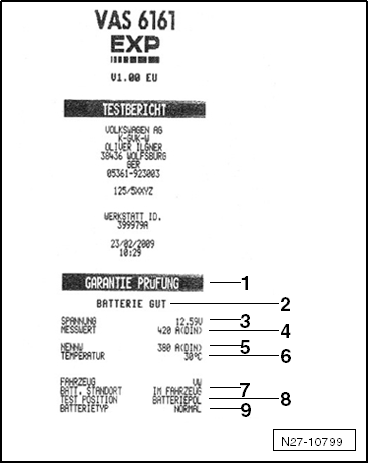
Explanation of Test Results
1 - Type of test
2 - Test result
3 - Measured voltage
4 - Battery -A- measured cold start value
5 - Battery -A- cold start value set on the Battery Tester -VAS6161-
6 - Temperature measured above the Battery -A-
7 - Battery -A- component location
8 - Battery terminal clamp position set on the Battery Tester -VAS6161-
9 - Selected battery type
Note
The printed test results are required for warranty claims.
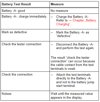
Test Result Evaluation
Evaluating the Battery Test Results for the Warranty and Service Tests
.png)
Evaluating the Battery Test Results for the Maintenance test
Battery Tester with Printer -VAS5097A-
WARNING
Risk of injury. Follow all warning messages and safety precautions. Refer to → Chapter "Warnings and Safety Precautions".
It is not necessary to disconnect or remove the Battery -A- when using the Battery Tester with Printer -VAS5097A-.
The following Batteries -A- can be tested using the Battery Tester with Printer -VAS5097A-:
- 80 to 499 A cold crank amps according to German Industry Standardization DIN (Deutsche Industrie Norm). Refer to → Note.
- 95 to 574 A cold cranking output according to IEC (International Engineering Consortium)
- 136 to 855 A cold cranking output according to EN/ SAE (Europäische Norm/ Standard of Automotive Engineers)
1) Batteries -A- with cold crank amps greater than 499 A according to DIN can be tested with the setting for 499 A according to DIN.
The Batteries -A- are tested by being loaded with current that corresponds to the starter current of a vehicle. Under this load, the Battery -A- is evaluated and the measured results are output through the printer.
Note
Read the Battery Tester with Printer -VAS5097A- Operating Instructions and Battery Tester with Printer -VAS5097A- Quick Reference Guide label on the Battery Tester with Printer -VAS5097A- and the cold crank amps table. Refer to → Chapter "Cold Crank Amps Table".
- Battery Tester with Printer -VAS5097A- device description. Refer to → Chapter "Battery Tester with Printer -VAS5097A- Device Description".
- Battery load test. Refer to → Chapter "Battery Load Test".
- Cold crank amps table. Refer to → Chapter "Cold Crank Amps Table".
- Battery load test results. Refer to → Chapter "Battery Load Test Results".
- Printed test results explanations. Refer to → Chapter "Printed Test Results Explanations".
- Test result evaluation. Refer to → Chapter "Test Result Evaluation".
Battery Tester with Printer -VAS5097A- Device Description
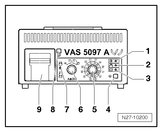
Battery Tester with Printer -VAS5097A-
1 - LED green, "Device in use"
2 - LED red, "Device connected with terminals reversed"
3 - LED red "Battery cannot be tested", the Battery -A- must be replaced.
4 - Start button
5 - Cold cranking output selector switch
6 - ON/OFF function switch
7 - Sliding switch (battery hook-up to the Battery -A-/at jump start point)
8 - Paper-feed -button
9 - Printer
Battery Load Test
WARNING
Risk of injury. Follow all warning messages and safety precautions. Refer to → Chapter "Warnings and Safety Precautions".
Special tools and workshop equipment required
- Battery Tester with Printer -VAS5097A-
Always note the TPL 2012182.
Procedure
WARNING
Do not check or charge a Battery -A- when the visual indicator has "no color or is bright yellow". Jump starting must not be used!
There is a risk of explosion during testing, charging or jump starting.
These Batteries -A- must be replaced.
Note
The Battery -A- temperature must be at least 10 ºC (50 ºF).
Caution
- Turn off the ignition and all electrical equipment.
- Remove the key.
- Check the visual indicator on Batteries -A- with visual indicator. Refer to → Chapter "Battery, Checking, Vehicles with Battery Monitoring Control Module J367 or Energy Management Control Module J644 and Data Bus On Board Diagnostic Interface J533".
- Switch on the Battery Tester with Printer -VAS5097A-. Refer to → Chapter "Battery Tester with Printer -VAS5097A- Device Description".
- Determine the cold crank amps according to specifications on the Battery -A- in ampere (A) according to DIN and determine the Battery Tester With Printer -VAS5097A- adjustment range using the table. Refer to → Chapter "Cold Crank Amps Table".
Note
If the Battery -A- does not state this value in DIN but rather in IEC or EN/SAE, then convert the value using the table (refer to → Chapter "Cold Crank Amps Table") or the table on the Battery Tester with Printer -VAS5097A-.
- Set the cold crank amps with the cold crank amps selector switch. Refer to → Chapter "Battery Tester with Printer -VAS5097A- Device Description".
- Set the measuring range (80 to 379 A or 380 to 499 A) using the ON/OFF switch. Refer to → Chapter "Battery Tester with Printer -VAS5097A- Device Description".
Note
Batteries -A- with cold crank amps greater than 499 A according to DIN can be tested with the setting for 499 A according to DIN.
- Connect the red terminal (+) to the positive terminal of the Battery -A-.
- Connect the black terminal (-) to the negative terminal for the Battery -A-.
Note
- Make sure the test terminals make good contact!
- Note TPL 2012182 for the Battery Tester with Printer -VAS5097A-.
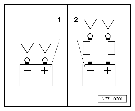
- Using the sliding switch, select the test clamp connection point. Refer to → Chapter "Battery Tester with Printer -VAS5097A- Device Description".
1 - Direct connection to the Battery -A-
2 - Connection on the battery jump start terminal
- Check if the cold crank amps indicated on the Battery -A- matches the selected value on the Battery Tester with Printer -VAS5097A-.
- Press theStart-button. Refer to → Chapter "Battery Tester with Printer -VAS5097A- Device Description".
The green LED lights up. Refer to → Chapter "Battery Tester with Printer -VAS5097A- Device Description". The test program runs automatically. The test results are output through the printer. Refer to → Chapter "Battery Load Test Results". If the Battery Tester with Printer -VAS5097A- does not start, (the LED does not come on and there is no print out), then charge the Battery -A-. Refer to → Chapter "Battery, Charging".
- Switch off the Battery Tester with Printer -VAS5097A-. Refer to → Chapter "Battery Tester with Printer -VAS5097A- Device Description".
- Remove the test terminals.
Note
- The test is over after approximately 20 seconds.
- The results of the test are output through the printer.
- Only perform the test once. Repeating the test will not produce accurate results.
- The Battery Tester with Printer -VAS5097A- needs 30 minutes to cool off before it is ready for the next measurement.
Cold Crank Amps Table
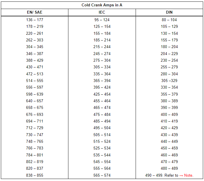
1) Batteries -A- with cold crank amps greater than 499 A according to DIN can be tested with the setting for 499 A according to DIN.
Battery Load Test Results
By placing the battery under a strong load during the Battery -A- load test, the battery voltage will be reduced.
- If the Battery -A- is good, the voltage drops only to the specified minimum voltage.
- If the Battery -A- is defective or weakly charged, the battery voltage will drop very quickly to below the specified minimum voltage.
- After testing, this low voltage level is maintained for a lengthy period and only increases again slowly.
- Only perform the test once. Repeating the test will not produce accurate results.
- In order to be able to test another/additional Battery -A-, the Battery Tester with Printer -VAS5097A- must cool down for approximately 30 minutes for the test result to be correct.
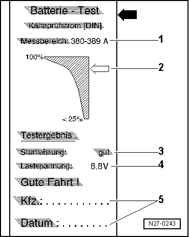
Printed Test Results Explanations
1 - Measuring range set on the Battery Tester with Printer -VAS5097A-
2 - Diagram, the -arrow- points to the Battery -A- status.
3 - Test result
4 - Battery -A- voltage during the battery load test.
5 - Vehicle data and date. For tester to fill out.
Note
- The printed test results are required for warranty claims.
- Only perform the test once. Repeating the test will not produce accurate results.
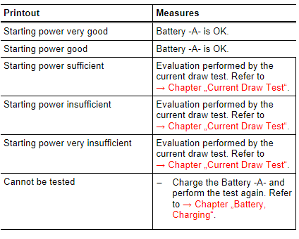
Test Result Evaluation
Current Draw Test
WARNING
Do not check or charge a Battery -A- when the visual indicator has "no color or is bright yellow". Jump starting must not be used!
There is a risk of explosion during testing, charging or jump starting.
These Batteries -A- must be replaced.
Make sure the correct charging mode is set on the battery charger so the current draw test is not inaccurate.
- Battery Charger -VAS5095A-. Refer to → Chapter "Battery, Charging with Battery Charger -VAS5095A-".
- Battery Charger -VAS5900-. Refer to → Chapter "Battery Charger -VAS5900-".
- Battery Charger -VAS5903-. Refer to → Chapter "Battery Charger -VAS5903-".
In order to receive an indication as quickly as possible of the battery condition of discharged Batteries -A-, a conclusion can be made during the charging process using the Battery -A- current draw as to whether the Battery -A- should be replaced or charged completely.
Note
In the case of the Battery Tester -VAS6161-, the current draw test must always be conducted when the test result "conduct current draw test" appears in the display.
The current draw test should always be performed if the test using the Battery Tester with Printer -VAS5097A- had the following results:
1 - Starting power sufficient
2 - Starting power insufficient
3 - Starting power very insufficient
4 - Cannot be tested - charge the Battery -A- and perform the test again
5 - Battery Tester with Printer -VAS5097A- does not turn on (no LED, no printout)
Depending on the test results Battery Tester with Printer -VAS5097A- (refer to → Chapter "Test Result Evaluation"), additional test steps or work for a clear evaluation of the battery charge must be made.
By checking a current draw capacity on a Battery -A- during the charging procedure, it can be determined in a short time whether a partially discharged or severely discharged Battery -A- can become operable again by further charging. Refer to → Chapter "Severely Discharged Batteries".
Test Prerequisites
- When charging a battery, the temperature of the battery must be at least 10 ºC (50 ºF).
- The charger must be able to deliver at least 30 A charge current, such as on the Battery Charger -VAS5095A-/Battery Charger -VAS5900-/Battery Charger -VAS5903-.
- When charging with the Battery Charger -VAS5095A-, the Battery -A- current draw must be measured using a current probe (Test Instrument Set - Current Clamp - 100A -VAS6356/4A-).
- The Battery Charger -VAS5900- and the Battery Charger -VAS5903- indicate the current draw.
Procedure
- Connect the Battery -A- to the Battery Charger and start the charging process.
- Measure the Battery -A- charge current after five minutes.
Test Result
The charge current must be above 10% of the nominal capacity 5 minutes after charging begins.
Example
With a 60 Ah battery, the charge current must be greater than 6 A 5 minutes after charging begins.
- Fully charge the Battery -A- if the charge current is higher than 10% of the nominal capacity.
- Let the Battery -A- sit for two hours and then perform the battery load test. Refer to → Chapter "Battery Load Test".
If the charge current is less than 10% of the nominal capacity (less than 6 A for a 60 Ah battery) five minutes after starting the charging, then replace the Battery -A-. Refer to → Electrical Equipment; Rep. Gr.27; Battery; Battery, Removing and Installing.
- In warranty and Goodwill cases, fill out the battery test sheet and keep it with the Battery -A-.
Battery, Checking Resting Voltage, Vehicles in Storage or Inventory
WARNING
Risk of injury. Follow all warning messages and safety precautions. Refer to → Chapter "Warnings and Safety Precautions".
Note
- The resting voltage may only be measured on vehicles in storage or inventory within the scope of the prescribed maintenance and care work as an assessment criteria for the Battery -A- condition.
- The resting voltage measurement serves to determine whether it is necessary to recharge the Battery -A- on vehicles in storage or inventory. Refer to →Maintenance Intervals; Rep. Gr.03.
Special tools and workshop equipment required
- Analog/Digital Multimeter -FLU83III-
Test Conditions
The Battery -A- may not be charged or discharged for at least two days.
Procedure
- Measure the Battery -A- resting voltage using the Analog/Digital Multimeter -FLU83III-.
Test Result
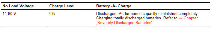
.png)
