Audi A6 Typ 4G: Connections for Quick-Release Coupling on Refrigerant Circuit
General Information
- Only valves and connections that are resistant to refrigerant R134a and refrigerant oil must be installed.
- Different connections (outer diameter) for high pressure and low pressure side.
- Discharge the refrigerant circuit before removing valves or valve inserts.
- Always screw on sealing caps.
Allocation in the vehicle. Refer to → Heating, Ventilation and Air Conditioning; Rep. Gr.87; System Overview - Refrigerant Circuit (vehicle-specific repair manual).
 WARNING
There is a danger of ice-up.
Refrigerant will leak out if refrigerant circuit is not discharged.
Refrigerant must be extracted before opening refrigerant circuit. If refrigerant circuit is not opened within 10 minutes of extraction, pressure may form in refrigerant circuit due to evaporation. Extract the refrigerant once more.
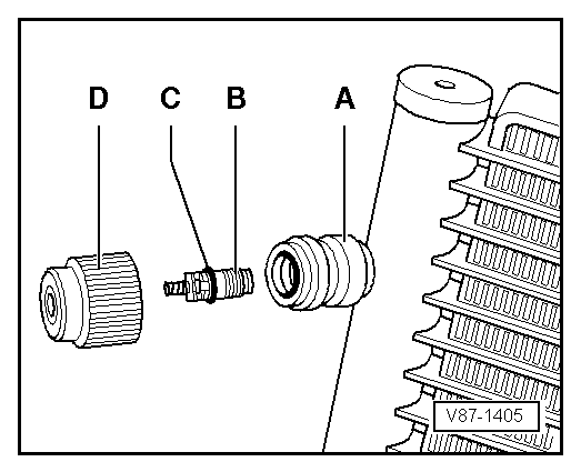
Connections with Schrader Valve (Needle Valve)
- -A- Service connection (soldered in)
- -B- valve insert (Schrader valve or needle valve)
- -C- O-ring (belonging to the valve)
- -D- cap with seal
 Note
Note
- After connecting, install the hand wheel for the service coupling just far enough into the quick-release coupling adapter until the valve is securely opened inside the service connection (pay attention to the pressure gauge, do not put too much pressure on the valve).
- For removing and installing the valve set -B- when the refrigerant circuit is evacuated, for example, use an adapter from the Refrigerant Sockets -T10364-.
- Tighten the valve insert -B- very carefully because the tightening specification is very small.
- There are different versions of these valves and therefore there are different tightening specifications. Valve insert -B- with a VG5 (5.2 x 0.7 mm, tire valve) thread has a tightening specification of 0.4 Nm +- 0.1 Nm; a valve insert with a M6 x 0.75 mm thread has a tightening specification of 0.9 Nm +- 0.1 Nm, and a valve insert with a M8 x 1.0 mm thread has a tightening specification of 2.0 Nm +- 0.2 Nm.
- There are different versions of these valves, valve inserts and their respective sealing caps. Be sure to use the correct valve version and the correct sealing cap allocation. Refer to the Parts Catalog.
Connections with Primary Sealing Valve (Ball Valve)
WARNING
Before unscrewing the connection, connect the service station and extract the refrigerant. Refrigerant circuit must be empty to avoid possible injury.
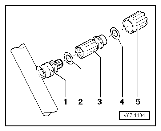
Connection with High-Pressure Valve
1 - Socket with internal thread (soldered in)
2 - O-ring (version and identification: black or colored. Refer to the Parts Catalog)
3 - Valve with an external thread and groove for the O-ring (identification: ball valve)
4 - Cap seal
5 - Sealing cap
The service connection on the high pressure side depends on the vehicle, not all operating conditions of the A/C system are on high pressure (for example on the Audi Q7 e-tron). For this reason to check the A/C function in these vehicles the sensor installed in the refrigerant circuit must be used. Refer to → Heating, Ventilation and Air Conditioning; Rep. Gr.87; Refrigerant Circuit and use the Vehicle Diagnostic Tester in the "Guided Fault Finding" function.
Note
- After connecting, install the hand wheel for the service coupling just far enough into the quick-release coupling adapter until the valve is securely opened inside the service connection (pay attention to the pressure gauge, do not put too much pressure on the valve).
- For removing and installing the valve -3- when the refrigerant circuit is evacuated, for example, use an adapter from the Refrigerant Sockets -T10364-.
- There are different versions of these valves (with internal or external threads). Therefore the tightening specifications can also differ. The valves -3- with an M12 x 1.5 mm external thread have a tightening specification of 9 Nm +-1 Nm.
- There are different versions of these valves and their respective caps. Be sure to use the correct valve version and the correct sealing cap allocation. Refer to the Parts Catalog.
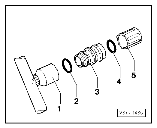
Connection with Low-Pressure Valve
1 - Socket with an external thread and groove for the o-ring (soldered in)
2 - O-ring (version and identification: black or colored. Refer to the Parts Catalog)
3 - Valve with an internal thread
4 - Cap seal
5 - Sealing cap
Note
- Install the hand wheel for the service coupling just far enough into the quick-release coupling adapter until the valve is securely opened inside the service connection (pay attention to the pressure gauge, do not put too much pressure on the valve).
- For removing and installing the valve -3- when the refrigerant circuit is evacuated, for example, use an adapter from the Refrigerant Sockets -T10364-.
- There are different versions of these valves (with internal or external threads). Therefore the tightening specifications can also differ. The currently used valves -3- with an M10 x 1.25 mm internal thread have a tightening specification of 9 Nm +- 1 Nm.
- There are different versions of these valves and their respective caps. Be sure to use the correct valve version and the correct sealing cap allocation. Refer to the Parts Catalog.