Audi A6 Typ 4G: Generator
Generator, Checking
Perform Generator Test
Vehicle Diagnostic Tester is attached.
- Select the Diagnostic mode and start the diagnostics.
- Select the tab Test Plan.
- Select Select Individual Tests and choose the following sequence.
- Body
- Electrical Equipment
- 27 - Starter, voltage supply
- Electrical Components
- C - Generator, Checking
The Vehicle Diagnostic Tester continues with the generator test from here on.
Overview - Generator, Bosch through MY 2000
1 - Bolts
- 1 Nm
2 - Cover
- With three tabs
3 - Bolts
- 2 Nm
4 - Voltage Regulator
- Removing:
- Remove the bolts -1- and remove the protective cap -2-.
- Remove the bolts -3- and remove the voltage regulator.
- Carbon brushes wear limit: 5 mm
5 - Generator
Overview - Bosch Generator from 2001
 Note
Note
The generators were implemented as a running change.
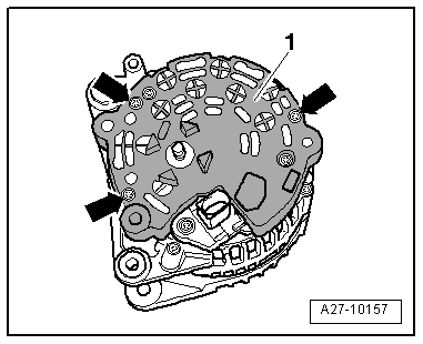
1 - Generator
2 - Voltage Regulator
- Removing and installing. Refer to → Chapter "Voltage Regulator, Bosch Generator from 2001, Removing and Installing".
- Carbon brushes, checking. Refer to → Chapter "Carbon Brushes, Checking, All Bosch Generators from 2001"
3 - Bolt
- 2.5 Nm
4 - Cover
5 - Nut
- 12 Nm
6 - Nut
- 30 Nm
7 - Bolt
- 3 Nm
8 - Bolt
- 1.5 Nm
Voltage Regulator, Bosch Generator from 2001, Removing and Installing
Removing
- Remove the generator. Refer to → Electrical Equipment; Rep. Gr.27; Generator; Generator, Removing and Installing.
- Remove the bolt -1- and the nuts -3- and -4-.
- Remove the cover -2- on the rear side of the generator.
- Remove the bolts -arrows-.
- Remove voltage regulator.
Installing
- When installing the voltage regulator, make sure the carbon brushes rest correctly on the slip rings.
Install in reverse order of removal, observing the following:
- Install the generator. Refer to → Electrical Equipment; Rep. Gr.27; Generator; Generator, Removing and Installing.
- Tightening specification. Refer to → Chapter "Overview - Bosch Generator from 2001".
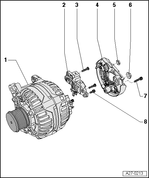
Overview - Bosch Generator from 2007
Note
The new generators are installed as a running change.
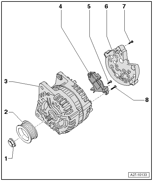
1 - Nut
- 65 Nm
2 - Ribbed Belt Pulley
3 - Generator
4 - Voltage Regulator
- Removing and installing. Refer to → Chapter "Voltage Regulator, Removing and Installing, Bosch Generator from 2007".
- Carbon brushes, checking. Refer to → Chapter "Carbon Brushes, Checking, All Bosch Generators from 2001"
5 - Bolt
- 1.5 Nm
6 - Cover
7 - Bolt
- 3 Nm
8 - Bolt
- 2.5 Nm
Voltage Regulator, Removing and Installing, Bosch Generator from 2007
Removing
- Remove the generator. Refer to → Electrical Equipment; Rep. Gr.27; Generator; Generator, Removing and Installing.
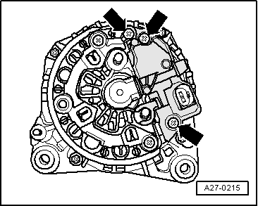
- Remove the bolts -arrows-.
- Remove the cover -1- on the rear side of the generator.
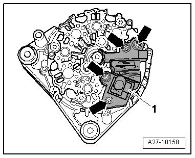
- Remove the bolts -arrows-.
- Remove voltage regulator -1-.
Installing
- When installing the voltage regulator, make sure the carbon brushes rest correctly on the slip rings.
Install in reverse order of removal, observing the following:
- Install the generator. Refer to → Electrical Equipment; Rep. Gr.27; Generator; Generator, Removing and Installing.
- Tightening specification. Refer to → Chapter "Overview - Bosch Generator from 2001".
Carbon Brushes, Checking, All Bosch Generators from 2001
Procedure
- Remove the voltage regulator: to 2007. Refer to → Chapter "Voltage Regulator, Bosch Generator from 2001, Removing and Installing", after 2007 → Chapter "Voltage Regulator, Removing and Installing, Bosch Generator from 2007".
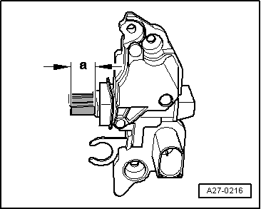
- Check the length -a- of the carbon brushes.
- Wear limit: -a- = 5 mm.
- Install the voltage regulator: to 2007. Refer to → Chapter "Voltage Regulator, Bosch Generator from 2001, Removing and Installing", after 2007 → Chapter "Voltage Regulator, Removing and Installing, Bosch Generator from 2007".
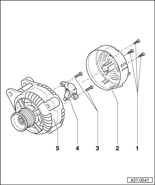
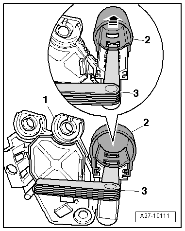
Overview - Generator, Valeo through MY 2000
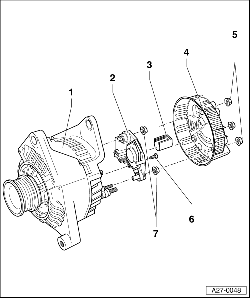
1 - Generator
2 - Voltage Regulator
- Removing:
- Remove the nuts -5- and the cover -4-.
- Remove the bolt -6- and the nuts -7- and remove the voltage regulator.
- Carbon brushes wear limit: 5 mm
3 - Protective Cap
4 - Cover
5 - Nut
- 2 Nm
6 - Bolt
- 2 Nm
7 - Nut
- 3.5 Nm
- Quantity: 2
Overview - Valeo Generator from 2001
Note
The generators were implemented as a running change.
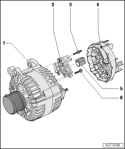
1 - Generator
2 - Voltage Regulator
- Removing and installing: to 2007. Refer to → Chapter "Voltage Regulator, Valeo Generator from 2001, Removing and Installing", after 2007 → Chapter "Voltage Regulator, Removing and Installing, Valeo Generator from 2007"
- Check the carbon brushes: to 2007. Refer to → Chapter "Carbon Brushes, Valeo Generator from 2001, Checking", after 2007 → Chapter "Carbon Brushes, Checking, Valeo Generator from 2007"
3 - Bolt
- 2 Nm
4 - Cover
5 - Protective Cap
6 - Bolt
- 2 Nm
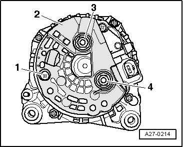
Voltage Regulator, Valeo Generator from 2001, Removing and Installing
Removing
- Remove the generator. Refer to → Electrical Equipment; Rep. Gr.27; Generator; Generator, Removing and Installing.
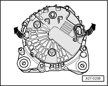
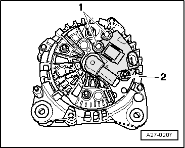
- Press the cover on the rear side of the generator off of the threaded pins -arrows-.
- Remove the bolts -1- and the double bolt -2-.
- Remove voltage regulator.
Installing
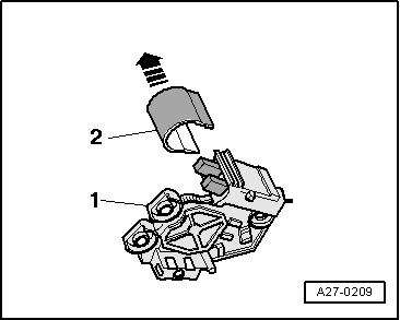
- Press the protective cap -2- off of the voltage regulator -1- in direction of -arrow-.
- When installing the voltage regulator, make sure the carbon brushes rest correctly on the slip rings.
- Install the protective cap with the voltage regulator installed.
Install in reverse order of removal, observing the following:
- Install the generator. Refer to → Electrical Equipment; Rep. Gr.27; Generator; Generator, Removing and Installing.
- Tightening specification. Refer to → Chapter "Overview - Valeo Generator from 2001".
Carbon Brushes, Valeo Generator from 2001, Checking
Procedure
- Remove voltage regulator. Refer to → Chapter "Voltage Regulator, Valeo Generator from 2001, Removing and Installing".
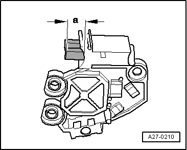
- Check the length -a- of the carbon brushes.
- Wear limit: -a- = 5 mm.
- Install the voltage regulator. Refer to → Chapter "Voltage Regulator, Valeo Generator from 2001, Removing and Installing".
Voltage Regulator, Removing and Installing, Valeo Generator from 2007
Special tools and workshop equipment required
- Feeler gauge 0.3 mm
Removing
- Remove the generator. Refer to → Electrical Equipment; Rep. Gr.27; Generator; Generator, Removing and Installing.
- Press the cover on the rear side of the generator off of the threaded pins -arrows-.
- Remove the bolts -1- and the double bolt -2-.
- Remove voltage regulator.
Installing
- Push a feeler gauge 0.3 mm -4- between the protective cap -2- and the carbon brushes -3-.
- Pull the protective cap off until the bar of the protective cap presses the carbon brushes down.
- After installation of the voltage regulator, press the protective cap all the way on.
Install in reverse order of removal, observing the following:
- Install the generator. Refer to → Electrical Equipment; Rep. Gr.27; Generator; Generator, Removing and Installing.
Tightening specification. Refer to → Chapter "Overview - Valeo Generator from 2001".
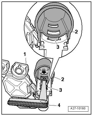
Carbon Brushes, Checking, Valeo Generator from 2007
Special tools and workshop equipment required
- Feeler gauge 0.3 mm
Procedure
- Remove voltage regulator. Refer to → Chapter "Voltage Regulator, Removing and Installing, Valeo Generator from 2007".
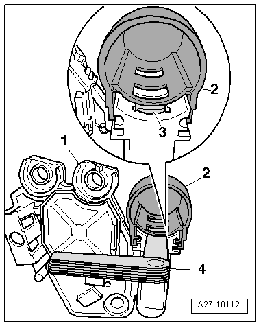
- Push a feeler gauge 0.3 mm -3- between the protective cap -2- and the carbon brushes.
- Remove the protective cap from voltage regulator -1--arrow-.
- Check the length -a- of the carbon brushes.
- Wear limit: -a- = 5 mm.
- With protective cap -2- installed, use feeler gauge -4- to press carbon brushes -3- down.
- Push the protective cap off -arrow- until the bar of the protective cap presses the carbon brushes down.
- Install the voltage regulator. Refer to → Chapter "Voltage Regulator, Removing and Installing, Valeo Generator from 2007".
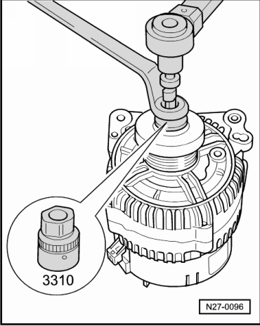
Ribbed Belt Pulley without Freewheel, Removing and Installing
Special tools and workshop equipment required
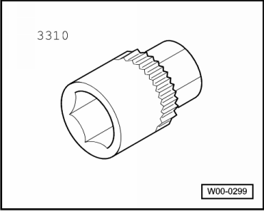
- Generator Belt Socket -3310-
- Inner hex socket 8 mm or TORX T50
Removing
- Remove the generator if necessary. Refer to → Electrical Equipment; Rep. Gr.27; Generator; Generator, Removing and Installing.
- For some engine types the removal can be performed with the generator still installed, here only the ribbed belt must have the tension released and be removed.
- If present, press the protective cap off the generator pulley.
- Counterhold nut using Generator Belt Socket -3310- and rotate generator shaft clockwise to loosen it.
- Remove ribbed belt pulley.
Installing
Install in reverse order of removal. Note the following:
- Turn the generator shaft counterclockwise to tighten.
- Clip protective cap onto generator pulley.
Tightening specification
.png)
Ribbed Belt Pulley with Freewheel, Removing and Installing
General Information
There are different ribbed belt pulley with freewheel.
Before removing check which special tool must be used for the removal of the ribbed belt pulley with freewheel.
 Caution
The length of the ribbed belt is different depending on the ribbed belt pulley with freewheel installed.
Check which ribbed belt pulley with freewheel is installed and make sure that the correct ribbed belt will be installed. For the ribbed belt allocation. Refer to the Parts Catalog.
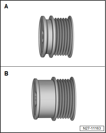
Characteristics of the Ribbed Belt Pulley with Freewheel
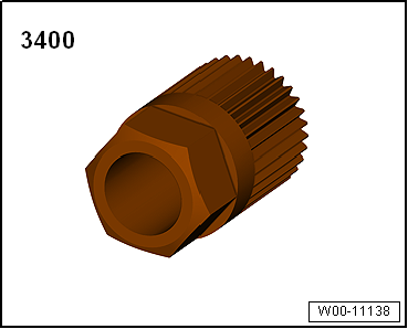
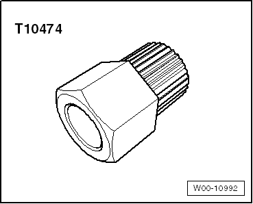
-A- small ribbed belt pulley with freewheel, special tool to be used Puller - Bevel Gear -T10474- or Multi-Tooth Adapter -3400-
-B- large ribbed belt pulley with freewheel, special tool to be used Multi-Tooth Adapter -3400-
Note
The ribbed belt for the large ribbed belt pulley with freewheel must be larger because it has a larger diameter.
Special tools and workshop equipment required
- Puller - Bevel Gear -T10474-
- Multi-Tooth Adapter -3400-
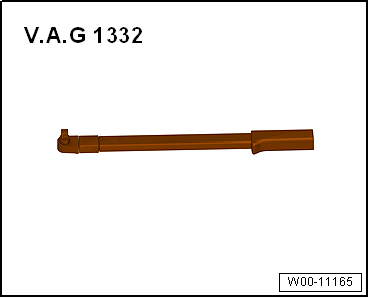
- Torque Wrench 1332 40-200Nm -VAG1332-
- Inner Hex Socket 8 mm or TORX T50
Removing
- Remove the generator if necessary. Refer to → Electrical Equipment; Rep. Gr.27; Generator; Generator, Removing and Installing.
- For some engine types the removal can be performed with the generator still installed, here only the ribbed belt must have the tension released and be removed.
- Clamp the generator in a vise at the mounting points.
- If equipped, remove the protective cap from the decoupling belt pulley with freewheel.
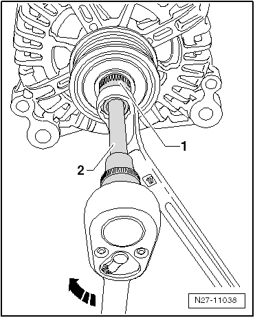
- Install the Multi-Tooth Adapter -T10474- or Multi-Tooth Adapter -3400--1- in the belt pulley and attach a wrench.
- Place a suitable tool -2- in the generator shaft.
- Turn the generator shaft clockwise in direction of -arrow- to loosen and while doing so counterhold with the wrench.
- Hold the ribbed belt pulley with freewheel in place by hand and turn it at the generator shaft until the ribbed belt pulley with freewheel can be removed.
Installing
Install in reverse order of removal. Note the following:
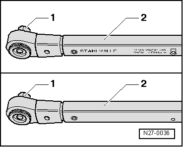
The Torque Wrench 1332 40-200Nm -VAG1332- must be rearranged for installing the decoupling belt pulley with freewheel as follows:
- Release the insert -1- and remove it from the handle part -2-.
- Turn the handle part -2- of the torque wrench 180º and reinsert the socket.
- Set the rotation direction of the torque wrench socket to "left".
- Next, screw the ribbed belt pulley with freewheel by hand onto the generator shaft until stop.
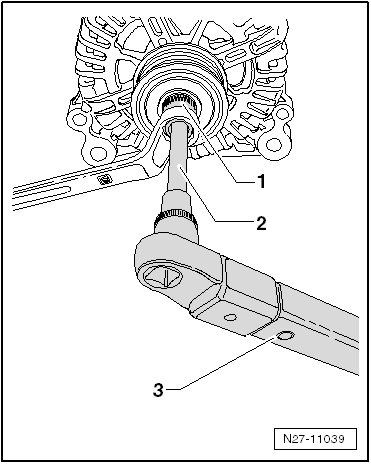
- Install the Multi-Tooth Adapter -T10474--1- ribbed belt pulley with freewheel and attach the wrench.
- Place a suitable tool -2- in the generator shaft.
- Turn the generator shaft using the Torque Wrench 1332 40-200Nm -VAG1332--3- counter clockwise to tighten the ribbed belt pulley with freewheel.
- Clip protective cap onto generator pulley.
Tightening Specification
.png)
Ribbed Belt Pulley with Freewheel, Checking
Procedure
- The ribbed belt pulley with freewheel is removed. Refer to → Chapter "Ribbed Belt Pulley with Freewheel, Removing and Installing".
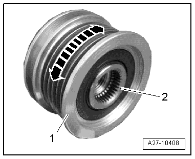
- Hold the inner ring -2- on the ribbed belt pulley with one hand using the thumb and index finger and the outer ring -1- with the other hand using the thumb and index finger.
- Hold the inner ring tight and turn the outer ring in the rotation direction of the generator.
- If the free-running hub is intact, the outer does not turn.
- Hold the inner ring tight and turn the outer ring opposite the rotation direction of the generator.
- If the free-running hub in intact, the outer ring turns with slight resistance.
Replace the ribbed belt pulley if the free-running hub does not function as described.
Special Tools
Special tools and workshop equipment required
- Analog/Digital Multimeter -FLU83III-
- Puller - Bevel Gear -T10474-
- Torque Wrench 1332 40-200Nm -VAG1332-
- Inner Hex Socket 8 mm or TORX T50
- Battery Charger -VAS5095A-
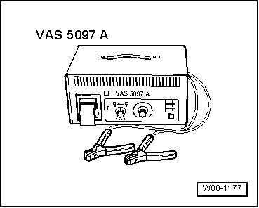
- Battery Tester with Printer -VAS5097A-
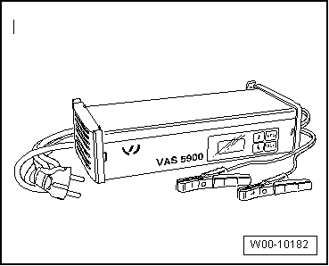
- Battery Charger -VAS5900-
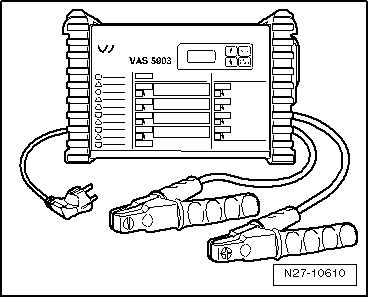
- Battery Charger -VAS5903-
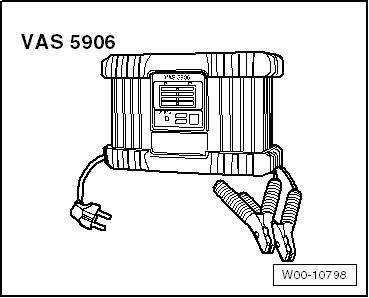
- Battery Charger -VAS5906-
- Solar Battery Maintainer -VAS6102A-
- Battery Tester -VAS6161-
- Generator Belt Socket -3310-
- Multi-Tooth Adapter -3400-