Audi A6 Typ 4G: Passenger Occupant Detection System
Component Location Overview - Passenger Occupant Detection System
Component Location Overview - Passenger Occupant Detection System
 WARNING
The replacement part (Service Kit) for the passenger occupant detection system (country-specific) is already pre-installed. Never disconnect the connector between the Passenger Occupant Detection System Control Module -J706- and the Passenger Occupant Detection System Pressure Sensor -G452-. The Service Kit differs depending on the seat version and consists of:
Standard seat/sport seat/super sport seat:
- Seat cushion with/without a seat heating element
- The Passenger Occupant Detection System Pressure Sensor -G452- is attached to the seat cushion.
- Passenger Occupant Detection System Control Module -J706-
Multi-contour seat:
- Passenger Occupant Detection System Pressure Sensor -G452- sewn in with seat heating element in the seat cover
- Passenger Occupant Detection System Control Module -J706-
WARNING
Follow all safety precautions when working on the passenger occupant detection system. Refer to → Chapter "Passenger Occupant Detection System Deactivation Additional Safety Precautions, Market-Specific".
 Note
Note
The passenger occupant detection system is only installed in the front passenger seat.
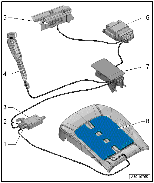
1 - Connector
- Between Passenger Occupant Detection System Pressure Sensor -G452- and Passenger Occupant Detection System Control Module -J706-
 Caution
Do not disconnect the connector between the Passenger Occupant Detection System Pressure Sensor -G452- and the Passenger Occupant Detection System Control Module -J706-.
2 - Connector
- Between the connector station under the seat and the Passenger Occupant Detection System Control Module -J706-.
3 - Passenger Occupant Detection System Control Module -J706-
- There are different versions. For the correct allocation. Refer to the Parts Catalog.
Caution
Do not disconnect the connector between the Passenger Occupant Detection System Pressure Sensor -G452- and the Passenger Occupant Detection System Control Module -J706-.
- Removing and installing. Refer to → Chapter "Passenger Occupant Detection System, Removing and Installing".
4 - Front Passenger Seat Belt Switch -E25- and Passenger Occupant Detection System Seat Belt Force Sensor -G453-
- Removing and installing. Refer to → Chapter "Front Seat Belt Latch, Removing and Installing".
5 - Front Passenger Airbag -Disabled- Indicator Lamp -K145-
- Removing and installing. Refer to → Electrical Equipment; Rep. Gr.96; Controls; Overview - Instrument Panel Controls.
6 - Airbag Control Module -J234-
- Removing and installing. Refer to → Chapter "Airbag Control Module -J234-, Removing and Installing".
7 - Connector Station
- Under the seat
- Connector assignment. Refer to → Wiring diagrams, Troubleshooting & Component locations.
- Connectors, disconnecting and connecting. Refer to → Chapter "Airbag Adapter, Connecting and Disconnecting".
8 - Passenger Occupant Detection System Pressure Sensor -G452-
- Different versions:
- Standard seat/sport seat/super sport: the passenger occupant detection sensor is glued to the seat cushion
- Multi-contour seat: the Multi-contour seat and seat heating element are sewn inside the seat cover
Caution
- Do not disconnect the connector between the Passenger Occupant Detection System Pressure Sensor -G452- and the Passenger Occupant Detection System Control Module -J706-.
- Never disconnect the passenger occupant detection sensor from the seat cushion or the seat cover.
- Removing and installing. Refer to → Chapter "Passenger Occupant Detection System, Removing and Installing".
Overview - Passenger Occupant Detection System
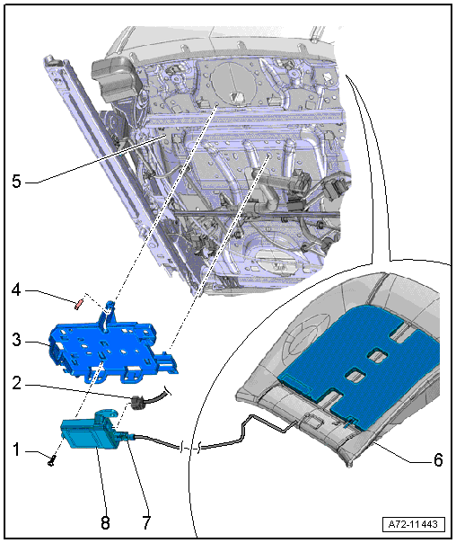
1 - Bolt
- 1.5 Nm
2 - Connector
- Between the connector station under the seat and the Passenger Occupant Detection System Control Module -J706-.
3 - Bracket
- For the control module
- Engaged and clipped in the seat pan
- Removing and installing. Refer to → Chapter "Front Seat Control Module Bracket, Removing and Installing".
4 - Pin
- for securing the bracket to the seat pan
5 - Front Seat
6 - Passenger Occupant Detection System Pressure Sensor -G452-
Caution
- Do not disconnect the connector between the Passenger Occupant Detection System Pressure Sensor -G452- and the Passenger Occupant Detection System Control Module -J706-.
- Never disconnect the passenger occupant detection sensor from the seat cushion or the seat cover.
- Different versions:
- Standard seat/sport seat/super sport: the passenger occupant detection sensor is glued to the seat cushion
- Multi-contour seat: the Multi-contour seat and seat heating element are sewn inside the seat cover
- Removing and installing. Refer to → Chapter "Passenger Occupant Detection System, Removing and Installing".
7 - Connector
- Between Passenger Occupant Detection System Pressure Sensor -G452- and Passenger Occupant Detection System Control Module -J706-
Caution
Do not disconnect the connector between the Passenger Occupant Detection System Pressure Sensor -G452- and the Passenger Occupant Detection System Control Module -J706-.
8 - Passenger Occupant Detection System Control Module -J706-
- clipped with the bracket
Caution
Do not disconnect the connector between the Passenger Occupant Detection System Pressure Sensor -G452- and the Passenger Occupant Detection System Control Module -J706-.
- Removing and installing. Refer to → Chapter "Passenger Occupant Detection System, Removing and Installing".
Passenger Occupant Detection System, Removing and Installing
Note
The passenger occupant detection system is only installed in the front passenger seat.
WARNING
The replacement part (Service Kit) for the passenger occupant detection system (country-specific) is already pre-installed. Never disconnect the connector between the Passenger Occupant Detection System Control Module -J706- and the Passenger Occupant Detection System Pressure Sensor -G452-. The Service Kit differs depending on the seat version and consists of:
Standard seat/sport seat/super sport seat:
- Seat cushion with/without a seat heating element
- The Passenger Occupant Detection System Pressure Sensor -G452- is attached to the seat cushion.
- Passenger Occupant Detection System Control Module -J706-
Multi-contour seat:
- Passenger Occupant Detection System Pressure Sensor -G452- sewn in with seat heating element in the seat cover
- Passenger Occupant Detection System Control Module -J706-
Removing
WARNING
- Follow all safety precautions when working with pyrotechnic components (refer to → Chapter "Pyrotechnic Components Safety Precautions") and on the passenger occupant detection system (refer to → Chapter "Passenger Occupant Detection System Deactivation Additional Safety Precautions, Market-Specific").
- Before handling pyrotechnic components (for example, disconnecting the connector), the person handling it must "discharge static electricity". This can be done by touching the door striker, for example.
- Disconnect the battery Ground (GND) cable with the ignition turned on. Refer to → Electrical Equipment; Rep. Gr.27; Battery; Battery, Disconnecting and Connecting.
- Remove the front passenger seat. Refer to → Chapter "Front Seat, Removing and Installing".
- Fasten the front seat on the Engine/Transmission Holder - Seat Repair Fixture -VAS6136-. Refer to → Chapter "Front Seat, Mounting on Fixture for Seat Repair".
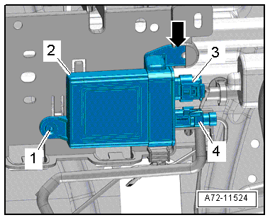
Caution
Never disconnect the connector -4- from the Passenger Occupant Detection System Control Module -J706-.
- Disconnect the connector -3- from the control module.
- Remove the bolt -1-.
- Disengage the control module -2- from the bracket -arrow- and free up the control module and wire.
Standard Seat (Manual or Power):
The Passenger Occupant Detection System Pressure Sensor -G452- is attached to the seat cushion.
- Remove seat cover with seat cushion for seat pan. Refer to → Chapter "Lower Seat Frame Cover and Cushion, Removing and Installing, Standard Seat".
- Separate the seat cover from the seat cushion. Refer to → Chapter "Seat Pan Cover and Cushion, Separating".
Manual or Power Sport Seat/Super Sport Seat
The Passenger Occupant Detection System Pressure Sensor -G452- is attached to the seat cushion.
- Remove the seat cover with the seat cushion for the Sport seat/Super Sport seat with the seat depth adjuster. Refer to → Chapter "Seat Pan Cover and Cushion, Removing and Installing, Sport Seat/Super-Sport Seat".
- Separate the seat cover from the seat cushion. Refer to → Chapter "Seat Pan Cover and Cushion, Separating".
Multi-Contour Seat
The Passenger Occupant Detection System Pressure Sensor -G452- is sewn in the seat cover with the seat heating element.
- Remove seat cover with seat cushion. Refer to → Chapter "Seat Pan Cover and Cushion, Removing and Installing, Multi-contour Seat".
- Separate the seat cover from the seat cushion. Refer to → Chapter "Seat Pan Cover and Cushion, Separating, Multi-contour Seat".
Installing
WARNING
- Follow all Safety Precautions when working with pyrotechnic components. Refer to → Chapter "Pyrotechnic Components Safety Precautions".
- Before handling pyrotechnic components (for example, connecting the connector), the person handling it must "discharge static electricity". This can be done by touching the door striker, for example.
Installation is performed in reverse order of removal, while noting the following:
Note
Make sure the connectors are installed correctly and are secure.
WARNING
Ignition must be on when connecting battery. If pyrotechnic components (for example, airbag, belt tensioner) are not repaired correctly, they may deploy unintentionally after connecting battery. There must not be anyone inside the vehicle when connecting the battery.
DANGER!
When working on vehicles with the ignition already switched on or that are ready to drive there is a danger of the engine starting unexpectedly and of being poisoned by gas in enclosed areas. Risk of body parts and/or clothing being clamped or pulled.
Perform the following before switching on the ignition:
- Move the selector lever into P.
- Activate the parking brake
- Turn off the ignition.
- Open the hood
- Connect the charger, such as the Battery Charger -VAS5095A- to the jump start of the 12V vehicle electrical system.
- Turn on the ignition.
- Connect the battery GND cable with the ignition turned on. Refer to → Electrical Equipment; Rep. Gr.27; Battery; Battery, Disconnecting and Connecting.
When installing a new service kit and after each repair on the front passenger seat where the seat and/or the backrest cover is "disengaged", a basic setting procedure must be performed on the passenger occupant detection system control module. Refer to → Chapter "Passenger Occupant Detection System Deactivation Additional Safety Precautions, Market-Specific".
- Select "airbag" in "Guided Fault Finding" to complete. Refer to Vehicle Diagnostic Tester.
- -J706 passenger occupant detection system control module basic setting
Note
If the Airbag Indicator Lamp -K75- signals a fault after installing, check the Diagnostic Trouble Code (DTC) memory, erase it and check it again. Refer to Vehicle Diagnostic Tester.
Installation notes, for example tightening specifications, replacing components. Refer to → Chapter "Component Location Overview - Passenger Occupant Detection System".
Special Tools
Special tools and workshop equipment required
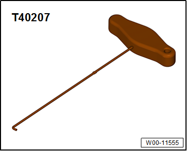
- Hook Tool -T40207-
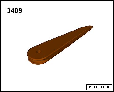
- Trim Removal Wedge -3409-
- Wiring Harness Repair Set - Hot Air Blower -VAS1978/14A-.