Audi A6 Typ 4G: Balancing
General Information
Before beginning balancing, the following requirements must be fulfilled.
- Tire inflation pressure must be OK.
- The tire tread must not be worn down on one side and should be at least 4 mm deep.
- The tire must not have any flat spots.
It is not possible to balance a flat spot.
- The tires must not have any damage such as cuts, holes, foreign debris, etc.
- The suspension, steering, tie rods and damper must be in proper working order.
- A road test has been performed.
Road Test, Performing Before Balancing
If a vehicle comes to the workshop with the complaint vibration, a road test must be performed before balancing the wheels.
- That way, information about the type of vibration can be obtained.
- Observe at which speed range the disturbance takes place.
- Raise the vehicle on the platform immediately after the road test.
- Mark the installation position on the tire.
- Remove wheels from vehicle.
 Caution
If brake pads are ceramics, wheel must not fall on brake disc, otherwise it will be irreparably damaged. To remove/install wheel, install long assembly pin instead of wheel bolts in top position (12:00 position) and short assembly pin in wheel bolt mounts for support. In this way, the wheel can glide on the assembly aids when removing/installing.
- Balance the wheels.
Stationary Balancing Machine
Special tools and workshop equipment required
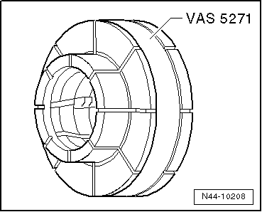
- Wheel Centering System Adapter -VAS5271-
- Wheel Balancer Clamping Adapter - 5 Lug -VAS6243-
 Note
Note
Please keep in mind that cleanliness is the most important when balancing as well, just as for any other repairs you perform. Only then can a proper result be obtained!
Caution
The balance weights must be glued on so that rub against the brake caliper or the suspension.
- Tension wheel on balancing machine.
Note
Wheels with a sensitive surface, glued-on wheel trim. Refer to → Chapter "Wheels with a Sensitive Surface, Glued-On Wheel Trim".
Note
- Be careful not to scratch off the glued- on wheel trim on these rims.
- The surface of the wheel trim is very sensitive.
- The rim will have be replaced if the wheel trim is damaged.
- The wheel trim cannot be replaced.
Dirt and rust in the area of the contact surfaces and centering of the wheel distort the result.
- Clean contact surfaces, centering seat and wheel disc before tensioning wheel on balancing machine!
- Tension wheel with tire on balancing machine.
Caution
The balance weights must be glued on so that rub against the brake caliper or the suspension.
Note
- To mount wheel on wheel balancer use, for example, the Wheel Centering System Adapter -VAS5271-.
- This way a 100% centering of the wheel and gentle mounting is possible!
- It is not possible to center it 100% on balancing machine with conical pensioners.
- With a deviation of 0.1 mm outside the center, there is an imbalance of 10 grams on the wheel/tire.
Note
- Use Wheel Balancer Clamping Adapter - 5 Lug -VAS6243- to gently mount a wheel on the wheel balancer.
- This way improved balance results are attained and the surface of the rim is protected, for example, on chrome wheel rims.
Wheels with a Sensitive Surface, Glued-On Wheel Trim
Special tools and workshop equipment required
- Tension Plate -VAS6652-
- Pressure Bolt -VAS6652/1-
Note
- Be careful not to scratch off the glued- on wheel trim on these rims.
- The surface of the wheel trim is very sensitive.
- The rim will have be replaced if the wheel trim is damaged.
- The wheel trim cannot be replaced.
Use only the Tension Plate -VAS6652- and the Pressure Bolt -VAS6652/1-.
Wheel/Tire Balancing Procedure
Note
Wheels with a sensitive surface, glued-on wheel trim. Refer to → Chapter "Wheels with a Sensitive Surface, Glued-On Wheel Trim".
Caution
The balance weights must be glued on so that rub against the brake caliper or the suspension.
Note
- Be careful not to scratch off the glued- on wheel trim on these rims.
- The surface of the wheel trim is very sensitive.
- The rim will have be replaced if the wheel trim is damaged.
- The wheel trim cannot be replaced.
- Let the wheel and tire rotate on the wheel balancer.
- Check the run of the characteristic lines on the sidewall of the tire in the area of the rim flange.
- Check the tire wear pattern while the wheel and tire are rotating.
Note
In the event of one-sided wear, flat spots from braking or severe wear spots, smooth running cannot be achieved by balancing. In this case, the tire must be replaced.
- Check the run-out of the wheel and tire. If the wheel with tire runs untrue although there are no flat spots, a radial or lateral run-out may be the cause.
- Check wheel with tire for radial and lateral run-out, radial run-out (RR) and lateral runout (LR)!
- If the radial and lateral run-out are within the specified tolerance, balance the wheel and tire.
Note
- Do not use more than 60 grams of weight per wheel.
- If more weight is necessary, a smoother running can achieved by matched mounting of the tire. Tires, matching.
- The display in the balancing machine should show 0 grams.
- Bolt the wheel to the vehicle.
Caution
If brake pads are ceramics, wheel must not fall on brake disc, otherwise it will be irreparably damaged. To remove/install wheel, install long assembly pin instead of wheel bolts in top position (12:00 position) and short assembly pin in wheel bolt mounts for support. In this way, the wheel can glide on the assembly aids when removing/installing.
- First tighten the bottom wheel bolt by hand to approximately 30 Nm.
- Now tighten the remaining wheel bolts diagonally also to about 30 Nm. This process centers the wheel on the wheel hub.
- Put the vehicle on its wheels.
- Now use a torque wrench to tighten the wheel bolts diagonally to the specified tightening specification.
- Carry out a road test.
Note
- If a vibration is still detected during the road test, the cause may be due to tolerance in the wheel centering.
- The component tolerances of wheels and wheel hubs can be additive in unfavorable cases. Vibration can result from this. This can be eliminated using a finish balancer.
Finish Balancer
Caution
For the balancing, the wheels of the tractive axle are set upon the turntable sensors, for example, front wheels for Front Wheel Drive (FWD) and all 4 wheels for All Wheel Drive (AWD).
Note
Working with a finish balancer requires instruction from the manufacturer of the balancer.
If it is determined when balancing on the vehicle the remaining imbalance is more than 20 grams, the wheel should be rotated on the wheel hub.
Note
- Be careful not to scratch off the glued- on wheel trim on these rims.
- The surface of the wheel trim is very sensitive.
- The rim will have be replaced if the wheel trim is damaged.
- The wheel trim cannot be replaced.
- Mark the point at which the imbalance is indicated.
Caution
The balance weights must be glued on so that rub against the brake caliper or the suspension.
- Afterwards, unbolt the wheel and rotate its position on the wheel hub so that the marking points downward.
Note
Important! The wheel hub must not turn during this procedure.
- First, tighten the lowest wheel bolt by hand to approximately 30 Nm.
- Now tighten the remaining wheel bolts diagonally also to about 30 Nm. This process centers the wheel properly on the wheel hub.
- Check again whether the imbalance is less than 20 grams using the finish balancer.
Note
The imbalance should not be smaller than 20 grams under any circumstances before changing balance weight.
- Remove the wheel bolts again if necessary.
- Rotate the wheel relative to the wheel hub once more by one or two wheel bolt holes.
- Tighten the wheels using the method described above.
Note
The imbalance should only be reduced by changing balance weight if the imbalance is less than 20 grams.
- Balance the wheels until the imbalance is below 5 grams.
- Tighten the wheel bolts to the specified tightening specification if you have not already done so.
- Always tighten the wheel bolts to the specified tightening specification using a torque wrench.
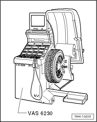
Hunter RFT33VAG Road Force Touch Wheel Balancer -VAS6230B4-
Wheels with a sensitive surface, glued-on wheel trim. Refer to → Chapter "Wheels with a Sensitive Surface, Glued-On Wheel Trim".
Expanded functions can be performed using Hunter RFT33VAG Road Force Touch Wheel Balancer -VAS6230B4- in addition to the previously known balancers.
A special characteristic of this system is testing the radial force of wheel/tire during rolling.
For this purpose, a roller presses a force of approximately 635 kg (1400 lb) against the wheel. This simulates the tire contact force against the street surface while driving.
Tire contact forces fluctuate due to radial- and lateral run-out and differing rigidity in the tires.
The Hunter RFT33VAG Road Force Touch Wheel Balancer -VAS6230B4- detects and stores the position of the maximum measured radial force in the tires. After that, the position of smallest dimension between rim flange and disc wheel center is measured.
Tire and Wheel Radial and Lateral Run-Out
Radial and lateral run-out occur when the wheel and tire are not running precisely true.
For technical reasons, 100% true running is not possible.
Therefore the manufacturers of these components allow a precisely specified tolerance.
Mounting the tire in a unfavorable position on the wheel can be the cause for exceeding the maximum allowed tolerance for wheel with tire.
The table shows the maximum permissible tolerance values for the wheel with mounted tire.
Tolerances for radial and lateral run-out of disc wheel with tire.
.png)
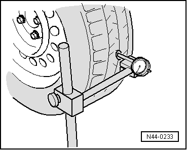
Radial and Lateral Run-out on Wheels/Tires, Checking with Tire Dial Gauge -VAG1435-
Checking lateral run-out:
- Preload tire dial gauge approximately 2 mm.
- Position dial gauge on tire side wall as shown in illustration.
- Slowly rotate the wheel.
- Note the smallest and the largest dial readings.
Note
If the difference is greater than 1.3 mm, the lateral run-out is too great.
In this case, lateral run-out can be reduced by matched mounting of the tire. Refer to → Chapter "Matching".
Peak values on the tire dial gauge due to small irregularities in the rubber may be disregarded.
Checking Radial Run-Out:
- Preload tire dial gauge approximately 2 mm.
- Position dial gauge on tire running surface as shown in illustration.
- Slowly rotate the wheel.
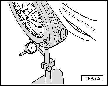
- Note the smallest and the largest dial readings.
Note
If the difference is greater than 1 mm, the radial run-out is too great.
In this case, radial run-out can be reduced by matched mounting of the tire. Refer to → Chapter "Matching".
Wheels and Tires, Radial and Lateral Run Out, Checking with Wheel Centering System Adapter -VAS5271-
Checking Lateral Run-Out:
- Mount the wheel on the wheel balancer.
Note
- Be careful not to scratch off the glued- on wheel trim on these rims.
- The surface of the wheel trim is very sensitive.
- The rim will have be replaced if the wheel trim is damaged.
- The wheel trim cannot be replaced.
- Use the Wheel Centering System Adapter -VAS5271-.
- Preload tire dial gauge approximately 2 mm.
- Position dial gauge on tire side wall as shown in illustration.
- Slowly rotate the wheel.
- Note the smallest and the largest dial readings.
Note
If the difference is greater than 1.3 mm, the lateral run-out is too great.
In this case, lateral run-out can be reduced by matched mounting of the tire. Refer to → Chapter "Matching".
Peak values on the tire dial gauge due to small irregularities in the rubber may be disregarded.
Checking Radial Run-Out
- Preload tire dial gauge approximately 2 mm.
- Position dial gauge on tire running surface as shown in illustration.
- Slowly rotate the wheel.
- Note the smallest and the largest dial readings.
Note
If the difference is greater than 1 mm, the radial run-out is too great.
In this case, radial run-out can be reduced by matched mounting of the tire.
Note
If the measured value exceeds the specified value, no acceptable smooth running can be attained.
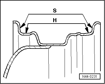
Rim Radial and Lateral Run-Out, Checking
- Mount the rim on the wheel balancer.
Note
- Be careful not to scratch off the glued- on wheel trim on these rims.
- The surface of the wheel trim is very sensitive.
- The rim will have be replaced if the wheel trim is damaged.
- The wheel trim cannot be replaced.
- Use the Wheel Centering System Adapter -VAS5271-.
- Preload tire dial gauge approximately 2 mm.
- Turn the rim slowly.
- Note the smallest and the largest dial readings.
S - Lateral Run-Out
H - Radial Run-Out
- Compare determined value with specifications in the table.
Note
Peak values on the tire dial gauge due to small irregularities may be disregarded.
Specifications for radial and lateral run-out on wheel
.png)
Note
If the measured value exceeds the specified value, no acceptable smooth running can be attained.
Matching
If radial or lateral run-out from wheel or tire meet each other, the untrue running of the wheel and tire is increased.
100% true running is not possible for technical reasons, , radial and lateral run-out on wheel/tire.
Under unfavorable circumstances, the lateral or radial run-out of the combined wheel and tire can exceed the permitted tolerance.
The individual values of the disc wheel and tire may nevertheless be below the specified value.
Targeted rotating of the tire relative to the wheel can partially balance out the radial and lateral run-out.
Tire specialists call this procedure match-mounting, whereby the true running of the wheel and tire can be optimized.
Drive the tires until they are warm before matching them to the tires already on the vehicle. This eliminates flat spots from standing which may exist.
Matching procedure:
Note
- Be careful not to scratch off the glued- on wheel trim on these rims.
- The surface of the wheel trim is very sensitive.
- The rim will have be replaced if the wheel trim is damaged.
- The wheel trim cannot be replaced.
- Let the air out of the tire.
- Press the tire beads off the rim flanges.
- Coat the tire beads all around with tire mounting paste.
- Rotate the tire 180º relative to the disc wheel.
- Inflate the tire to approximately 4 bar (58 psi).
- Tension wheel with tire on balancing machine.
- Check the run-out or the radial and lateral run-out, as necessary.
Note
- If the radial and lateral run-out value is not exceeded, the wheel can be balanced to 0 grams. Specifications.
- If the radial and lateral run-out lies outside the specified values, the tire must be turned again.
- Let the air out of the tire and press the tire beads off the rim flanges.
- Rotate the tire 90º (one quarter turn) relative to the disc wheel.
- Inflate the tire to 4 bar (58 psi) and check for true running.
Note
- If the radial and lateral run-out value is not exceeded, the wheel can be balanced to 0 grams.
- If the radial and lateral run-out is still outside the specified values, the wheel must be turned again.
- Press the tire beads off the rim flanges.
- Rotate the tire 180º (one half turn) relative to the disc wheel.
If the values for radial or lateral run-out are still outside the specified values, check the wheel for radial and lateral run-out.
If the measured values for radial and lateral run-out of the wheel disc are within the specified values, then the tire has excessive radial or lateral run-out. In this case, the tire must be replaced.
