Audi A6 Typ 4G: Battery Interrupt Igniter
Overview - Battery Interrupt Igniter
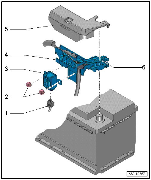
1 - Connector
- For the Battery Interrupt Igniter -N253-
- Releasing and removing
2 - Nuts
- 15 Nm
3 - Battery Interrupt Igniter -N253-
- Available only together with -4-
- Removing and installing. Refer to → Chapter "Battery Interrupt Igniter, Removing and Installing".
4 - Fuse Panel A -SA-
- Available only together with -3-
- Removing and installing. Refer to → Electrical Equipment; Rep. Gr.27; Battery; Overview - Battery.
5 - Cover
- For Fuse Panel A -SA-
6 - Positive Terminal Clamp
- Tightening specification. Refer to → Electrical Equipment; Rep. Gr.27; Battery; Overview - Battery.
Battery Interrupt Igniter, Removing and Installing
Special tools and workshop equipment required
- Vehicle Diagnostic Tester
Removing
 WARNING
- Follow all Safety Precautions when working with pyrotechnic components. Refer to → Chapter "Pyrotechnic Components Safety Precautions".
- Follow all regulations when disposing of pyrotechnic components. Refer to → Chapter "Airbag, Belt Tensioner and Battery Cut-Out Units, Storing, Transporting and Disposing".
 Note
Note
- If Airbag Indicator Lamp -K75- comes on after a vehicle accident, check whether crash data is stored using Vehicle Diagnostic Tester. If this is the case, check if the malfunction "Resistance too high" for the Battery Interrupt Igniter -N253- is stored in the Diagnostic Trouble Code (DTC) memory. If this is the case, Battery Interrupt Igniter -N253- must be replaced.
- The Battery Interrupt Igniter -N253- interrupts the circuit electrically each time an airbag is deployed. The Battery Interrupt Igniter -N253- must always be replaced after a deployment.
- The Battery Interrupt Igniter -N253- is available as a replacement part only together with Fuse Panel A -SA-.
- When just replacing the battery interrupt igniter -N253-, remove it from the replacement part and install it in Fuse Panel A -SA- as follows.
- A6 hybrid: remove the front outlet air guide for the traction battery. Refer to → Heating, Ventilation and Air Conditioning; Rep. Gr.87; Battery Cooling Module; Overview - Battery Cooling Module.
- Disconnect the battery Ground (GND) cable with the ignition turned on. Refer to → Electrical Equipment; Rep. Gr.27; Battery; Battery, Disconnecting and Connecting.
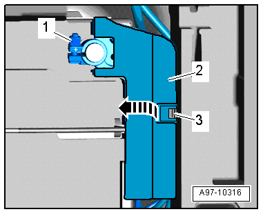
- Remove the nuts -2 and 3-.
- Release the retaining spring -3-.
- Lift the lid -2- over the Fuse Panel A -SA- slightly upward -arrow- and at the same time remove the battery interrupt igniter.
Note
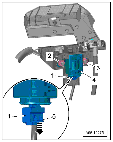
Ignore item -1-.
WARNING
Before handling pyrotechnic components (for example, disconnecting the connector), the person handling it must "discharge static electricity". This can be done by touching the door striker, for example.
- Remove battery interrupt igniter -4-.
- Press and remove the lock -5--arrow- and disconnect the connector -1-.
Installing
WARNING
- Follow all Safety Precautions when working with pyrotechnic components. Refer to → Chapter "Pyrotechnic Components Safety Precautions".
- Before handling pyrotechnic components (for example, connecting the connector), the person handling it must "discharge static electricity". This can be done by touching the door striker, for example.
Install in reverse order of removal. Note the following:
Note
Make sure the connectors are installed correctly and are secure.
WARNING
Ignition must be on when connecting battery. If pyrotechnic components (for example, airbag, belt tensioner) are not repaired correctly, they may deploy unintentionally after connecting battery. There must not be anyone inside the vehicle when connecting the battery.
DANGER!
When working on vehicles with the ignition already switched on or that are ready to drive there is a danger of the engine starting unexpectedly and of being poisoned by gas in enclosed areas. Risk of body parts and/or clothing being clamped or pulled.
Perform the following before switching on the ignition:
- Move the selector lever into P.
- Activate the parking brake
- Turn off the ignition.
- Open the hood
- Connect the charger, such as the Battery Charger -VAS5095A- to the jump start of the 12V vehicle electrical system.
- Turn on the ignition.
- Connect the battery GND cable with the ignition turned on. Refer to → Electrical Equipment; Rep. Gr.27; Battery; Battery, Disconnecting and Connecting.
- Check the DTC memory for the Airbag Control Module -J234- and correct any error if necessary using the Vehicle Diagnostic Tester.
Installation notes, for example tightening specifications, replacing components. Refer to → Chapter "Overview - Battery Interrupt Igniter".
