Audi A6 Typ 4G: Driver Side Airbag
Overview - Driver Side Airbag
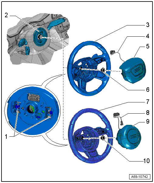
1 - Locking Bracket
- Use a T25 TORX screwdriver, approximately 100 mm long
2 - Steering Column Electronics Control Module -J527-
- With Airbag Spiral Spring/Return Spring with Slip Ring -F138- and Steering Angle Sensor -G85-
- Removing and installing. Refer to → Electrical Equipment; Rep. Gr.94; Steering Column Switch Module; Steering Column Electronics Control ModuleJ527, Removing and Installing.
3 - 4-Spoke Steering Wheel
- Equipment levels
- Removing and installing. Refer to → Suspension, Wheels, Steering; Rep. Gr.48; Steering Wheel; Steering Wheel, Removing and Installing.
4 - Wiring Harness
- For Driver Airbag Igniter -N95- and Driver Airbag Release Valve Igniter -N490-
- Replacing. Refer to → Chapter "Airbag Connector, Replacing".
- Press in to secure in the pockets on the steering wheel.
5 - Driver Side Airbag
- With the Driver Airbag Igniter -N95- and Driver Airbag Release Valve Igniter -N490-
 WARNING
Follow all Safety Precautions when working with pyrotechnic components. Refer to → Chapter "Pyrotechnic Components Safety Precautions".
- Removing and installing. Refer to → Chapter "Airbag Unit with Igniter, Removing and Installing".
6 - Bolt
- Tightening specification. Refer to → Suspension, Wheels, Steering; Rep. Gr.48; Steering Wheel; Overview - Steering Wheel.
7 - 3-Spoke-Steering Wheel
- Equipment levels
- Removing and installing. Refer to → Suspension, Wheels, Steering; Rep. Gr.48; Steering Wheel; Steering Wheel, Removing and Installing.
8 - Wiring Harness
- For Driver Airbag Igniter -N95- and Driver Airbag Release Valve Igniter -N490-
- Replacing. Refer to → Chapter "Airbag Connector, Replacing".
- Press in to secure in the pockets on the steering wheel.
9 - Driver Side Airbag
- With the Driver Airbag Igniter -N95- and Driver Airbag Release Valve Igniter -N490-
WARNING
Follow all Safety Precautions when working with pyrotechnic components. Refer to → Chapter "Pyrotechnic Components Safety Precautions".
- Removing and installing. Refer to → Chapter "Airbag Unit with Igniter, Removing and Installing".
10 - Bolt
- Tightening specification. Refer to → Suspension, Wheels, Steering; Rep. Gr.48; Steering Wheel; Overview - Steering Wheel.
Airbag Unit with Igniter, Removing and Installing
Special tools and workshop equipment required
- TORX screwdriver T25, approximately 100 mm long, commercially available
Removing
WARNING
- Follow all Safety Precautions when working with pyrotechnic components. Refer to → Chapter "Pyrotechnic Components Safety Precautions".
- Follow all regulations when disposing of pyrotechnic components. Refer to → Chapter "Airbag, Belt Tensioner and Battery Cut-Out Units, Storing, Transporting and Disposing".
- Move the steering wheel as far down as possible.
- Disconnect the battery ground cable with the ignition turned on. Refer to → Electrical Equipment; Rep. Gr.27; Battery; Battery, Disconnecting and Connecting.
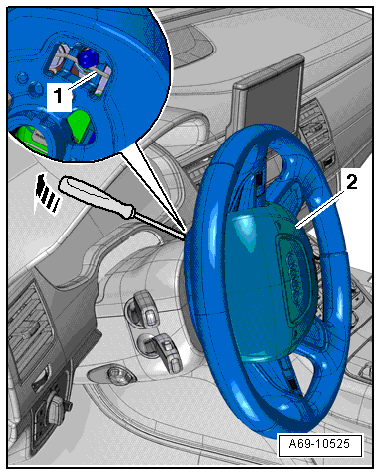
- Turn the steering wheel so the opening on the rear side of it faces upward. This is approximately the 12:00 position.
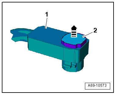
- Releases the locking bracket -1- for the driver side airbag -2--arrow-. Use a T25 TORX screwdriver, approximately 100 mm long.
 Note
Note
Electrical wires can be damaged with a flat-head screwdriver.
- Turn the steering wheel 180º and repeat the procedure on the opposite side.
- Bring the steering wheel back into the center (wheels are straight).
WARNING
Before handling pyrotechnic components (for example, disconnecting the connector), the person handling it must "discharge static electricity". This can be done by touching the door striker, for example.
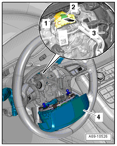
- Remove the driver airbag -4- from the steering wheel slightly.
- Pull out the connector lock -2--arrow- and press it down, disconnect the connector -1-.
- Vehicles with a multifunction and Tiptronic steering wheel: Disconnect the connector -3-.
- Remove the airbag.
WARNING
Set the airbag down so the impact cushion faces upward.
Installing
WARNING
- Follow all Safety Precautions when working with pyrotechnic components. Refer to → Chapter "Pyrotechnic Components Safety Precautions".
- Before handling pyrotechnic components (for example, connecting the connector), the person handling it must "discharge static electricity". This can be done by touching the door striker, for example.
Install in reverse order of removal. Note the following:
Note
- Make sure the connectors are installed correctly and are secure.
- Make sure the wires do not get caught.
- Connect the spiral spring electrical connector with the airbag connector coupling on the coil connector with slip ring.
- Press in harness connector to secure in the pockets on the steering wheel.
- Position driver airbag in the steering wheel and press on it until it audibly engages.
WARNING
Ignition must be on when connecting battery. If pyrotechnic components (for example, airbag, belt tensioner) are not repaired correctly, they may deploy unintentionally after connecting battery. There must not be anyone inside the vehicle when connecting the battery.
DANGER!
When working on vehicles with the ignition already switched on or that are ready to drive there is a danger of the engine starting unexpectedly and of being poisoned by gas in enclosed areas. Risk of body parts and/or clothing being clamped or pulled.
Perform the following before switching on the ignition:
- Move the selector lever into P.
- Activate the parking brake
- Turn off the ignition.
- Open the hood
- Connect the charger, such as the Battery Charger -VAS5095A- to the jump start of the 12V vehicle electrical system.
- Turn on the ignition.
- Connect the battery GND cable with the ignition turned on. Refer to → Electrical Equipment; Rep. Gr.27; Battery; Battery, Disconnecting and Connecting.
- Check and erase the airbag control module Diagnostic Trouble Code (DTC) memory so that faults can be stored when the connectors are disconnected. Refer to Vehicle Diagnostic Tester.
Installation notes, for example tightening specifications, replacing components. Refer to → Chapter "Overview - Driver Side Airbag".
Airbag Connector, Replacing
Removing
WARNING
Follow all Safety Precautions when working with pyrotechnic components. Refer to → Chapter "Pyrotechnic Components Safety Precautions".
- Remove the driver side airbag. Refer to → Chapter "Airbag Unit with Igniter, Removing and Installing".
Vehicles with A 3-Spoke Steering Wheel:
WARNING
Before handling pyrotechnic components (for example, disconnecting the connector), the person handling it must "discharge static electricity". This can be done by touching the door striker, for example.
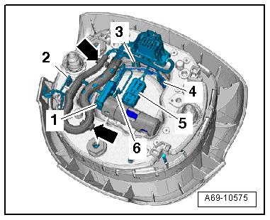
- Unclip the wiring harness from the brackets -arrows-.
- Disconnect the connectors -1, 2 and 4-.
- Disconnect and remove the connectors -3 and 5- for the Driver Airbag Igniter -N95-/Driver Airbag Release Valve Igniter -N490-.
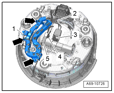
- Release the connector lock -2- with a small screwdriver in direction of -arrow- and disconnect the connector -1-.
Versions with 4-Spoke Steering Wheel
WARNING
Before handling pyrotechnic components (for example, disconnecting the connector), the person handling it must "discharge static electricity". This can be done by touching the door striker, for example.
- Unclip the wiring harness from the brackets -arrows-.
- Disconnect the connectors -2, 3, 4 and 6- by releasing the tabs.
- Disconnect the connectors -1 and 5- for the Driver Airbag Igniter -N95-/Driver Airbag Release Valve Igniter -N490-.
- Release the connector lock -2- with a small screwdriver -arrow- and disconnect the connector -1-.
Installing
WARNING
- Follow all Safety Precautions when working with pyrotechnic components. Refer to → Chapter "Pyrotechnic Components Safety Precautions".
- Before handling pyrotechnic components (for example, connecting the connector), the person handling it must "discharge static electricity". This can be done by touching the door striker, for example.
Install in reverse order of removal. Note the following:
Note
Make sure the connectors are installed correctly and are secure.
Installation notes, for example tightening specifications, replacing components. Refer to → Chapter "Overview - Driver Side Airbag".
