Audi A6 Typ 4G: Connector Assignments
Navigation Connector Assignment, 7T2
Information Electronics Control Module 1 -J794-
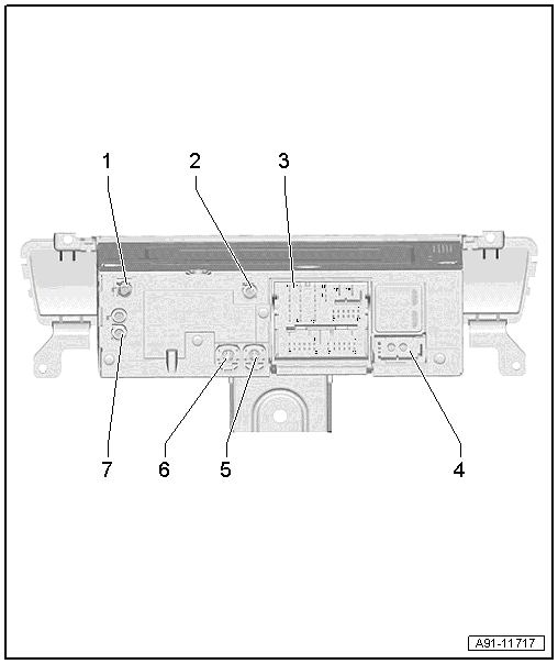
1 - DAB Connection from Antenna Amplifier 3 -R112-, Digital Radio Antenna -R183-, QV3
- SAT connection from Roof Antenna -R216-, Satellite Antenna -R170-, only USA and QV8
2 - GPS Connection from the Roof Antenna -R216-
3 - Connection Block with Four Multi-Pin Connectors
4 - MOST Bus
5 - 4-Pin Connector -T4z- to the External Audio Source Connection -R199-
6 - 4-Pin Connector -T4df- to the Front Information Display Control Head -J685-
7 - AM/FM/FM2 Antenna Connection
 Note
Note
Unlisted connector terminals are not assigned.
3 - Connection block with four multi-pin connectors
A - 8-Pin Connector -T8e-
1 - Right rear speaker (+)
2 - Right front speaker (+)
3 - Left front speaker (+)
4 - Left rear speaker (+)
5 - Right rear speaker (-)
6 - Right front speaker (-)
7 - Left front speaker (-)
8 - Left rear speaker (-)
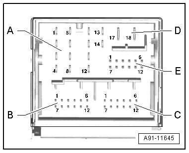
B - 12-Pin Connector -T12c-
1 - Data from Multimedia System Control Head -E380-
2 - Res BT Multimedia System Control Head -E380-
3 - Not Assigned
4 - Microphone input (+) from Microphone Unit in Front Roof Module -R164-, Left Front Microphone -R140-
5 - CVBS cable (-) for the Rearview Camera System Control Module -J772-
6 - Not Assigned
7 - Data to the Multimedia System Control Head -E380-
8 - Wake UP Multimedia System Control Head -E380-
9 - Res HU to the Multimedia System Control Head -E380-
10 - Not Assigned
11 - CVBS cable (+) for the Rearview Camera System Control Module -J772-
12 - Microphone input (-) for the Microphone Unit in Front Roof Module -R164-, Left Front Microphone -R140-
C - 12-Pin Connector -T12e-
All pins are connected to the External Audio Source Connection -R199-.
1 - LF-In ground
2 - Right LF-In
3 - USB, +5 V
4 - USB, ground
5 - iPod, ACC Power
6 - Detect
7 - Left LF-In
8 - LF-In ground shielding
9 - CVBS cable (+)
10 - CVBS cable (-)
11 - iPod data
12 - iPod data
D - 8-Pin Connector -T8f-
9 - Subwoofer -R211-
10 - Center Speaker -R208-
13 - Subwoofer -R211-
14 - Center Speaker -R208-
17 - Terminal 31
18 - Terminal 30
E - 12-Pin Connector -T12d-
7 - Ring-break Diagnostic Cable
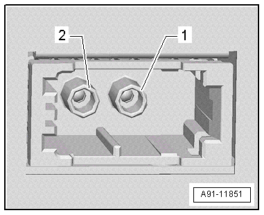
4 - MOST Bus
1 - Output
2 - Input
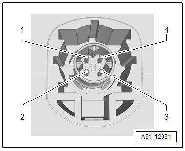
5 - 4-Pin Connector -T4z-
All pins are connected to the External Audio Source Connection -R199-.
1 - D (+)
2 - iPod recognized
3 - D (-)
4 - Ground
6 - 4-Pin Connector -T4df-
All pins are connected to the Front Information Display Control Head -J685-.
1 - LVDS (-)
2 - LIN
3 - LVDS (+)
4 - Ground
Chip Card Reader Control Module -J676- Connector Assignment, through MY 2014
Chip Card Reader Control Module -J676-
Note
Unlisted connector terminals are not assigned.
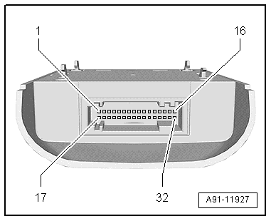
32-Pin Connector -T32p-
1-16 - to the Traffic Data Antenna -R173-
17 - VICS data wire to the Information Electronics Control Module 1 -J794-
19 - VICS data wire to the Information Electronics Control Module 1 -J794-
21 - Switch-on signal to the Information Electronics Control Module 1 -J794-
22 - Terminal 30
23 - ETC data to the Information Electronics Control Module 1 -J794-
25 - ETC data from the Information Electronics Control Module 1 -J794-
28 - Terminal 31
Chip Card Reader Control Module -J676- Connector Assignment, from MY 2015
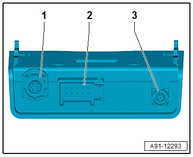
Chip Card Reader Control Module -J676-
1 - 5-Pin Connector -T5br- to the front External Audio Source Connection -R199-, USB quantity: 2, AUX IN
2 - 10-Pin Connector - T10bk-
3 - Connection from the Close Range Communication Antenna -R269-
1 - 5-Pin Connector -T5br-
All pins are connected to the External Audio Source Connection -R199-.
1 - Data (+)
2 - USB, +5 V
3 - Data (-)
4 - USB, ground
5 - Ground Shielding
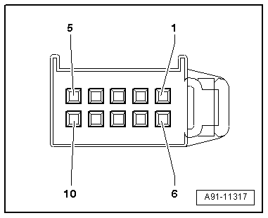
10-Pin Connector - T10bk-
1 - Supply (+) Traffic Data Antenna -R173-
2 - Supply (-) Traffic Data Antenna -R173-
3 - VICS data wire to the Traffic Data Antenna -R173-
4 - VICS data wire from the Traffic Data Antenna -R173-
5 - Not Assigned
6 - Not Assigned
7 - Diagnosis 1 Traffic Data Antenna -R173-
8 - Diagnosis 2 Traffic Data Antenna -R173-
9 - Terminal 30
10 - Terminal 31
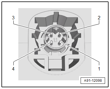
Chip Card Reader Control Module, Removing and Installing
The Chip Card Reader Control Module -J676- is located inside the glove compartment.
Removing
- Turn off the ignition and all electrical consumers and remove the ignition key.
- Open the glove compartment.
- Remove the chip card.
- Slide the Chip Card Reader Control Module -J676--1- back until it can be removed from the trim.
- Remove the clip -4-.
- Release and disconnect the connector -3- from the Chip Card Reader Control Module -J676--1-.
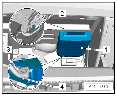
Installing
- Connect the connector -3- and then push the clip -4- through the opening.
- Make sure that all of the tabs -2- on the Chip Card Reader Control Module -J676--1- engage into the trim.
