Audi A6 Typ 4G: Connectors
Overview - Connector
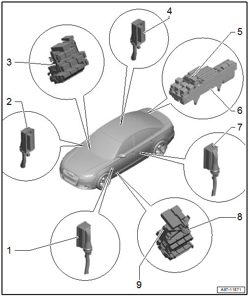
1 - Left Front Door Cut-Off Connector
- Disconnecting. Refer to → Chapter "Front Door Cut-Off Connector, Disconnecting".
2 - Right Front Door Cut-Off Connector
- Disconnecting. Refer to → Chapter "Front Door Cut-Off Connector, Disconnecting".
3 - Connector Station on Right A-Pillar
- Removing and installing. Refer to → Chapter "Right A-Pillar Connector Station, Removing and Installing".
4 - Right Rear Door Cut-Off Connector
- Disconnecting. Refer to → Chapter "Rear Door Cut-Off Connector, Disconnecting".
5 - 46-Pin Connector -T46b-
- Removing and installing. Refer to → Chapter "Luggage Compartment CAN Cut-Off Connector, Removing and Installing, 46-Pin Connector -T46b-".
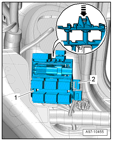
6 - Relay and Fuse Panel F -SF-
7 - Left Rear Door Cut-Off Connector
- Disconnecting. Refer to → Chapter "Rear Door Cut-Off Connector, Disconnecting".
8 - Connector Station on Left A-Pillar
- Removing and installing. Refer to → Chapter "Left A-Pillar Connector Station, Removing and Installing".
9 - 46-Pin Connector -T46a-
- Removing and installing. Refer to → Chapter "CAN Cut-Off Connector, Removing and Installing, 46-Pin Connector -T46a-".
CAN Cut-Off Connector, Removing and Installing
CAN Cut-Off Connector, Removing and Installing, 46-Pin Connector -T46a-
Removing
- Remove the front sill panel. Refer to → Body Interior; Rep. Gr.70; Passenger Compartment Trim; Sill Panel Strip, Removing and Installing.
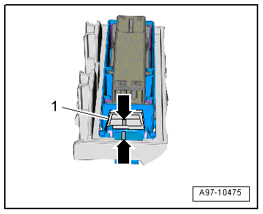
- Press the tabs -1- and unlock the bracket in direction of -arrow-.
- Disconnect the connector -2-.
 Note
Note
Check the exact connector assignment in the current wiring diagram → Wiring diagrams, Troubleshooting & Component locations.
Installing
Install in reverse order of removal.
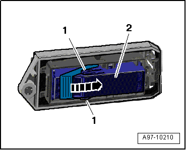
Luggage Compartment CAN Cut-Off Connector, Removing and Installing, 46-Pin Connector -T46b-
Removing
- Remove the luggage compartment right side trim panel cover.
- Press the tabs -1- and unlock the bracket in direction of -arrow-.
- Disconnect the connector -2-.
Note
Check the exact connector assignment in the current wiring diagram → Wiring diagrams, Troubleshooting & Component locations.
Installing
Install in reverse order of removal.
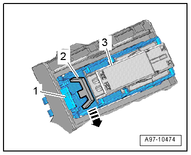
CAN Cut-Off Connector Mount, Removing and Installing
Removing
- Left CAN cut-off connector: Remove the connector station from the A-pillar on the left side. Refer to → Chapter "Left A-Pillar Connector Station, Removing and Installing".
- Luggage compartment CAN cut-off connector: Remove the relay and fuse panel inside the luggage compartment on the right side. Refer to → Chapter "Fuse Panel F -SF- in Right Luggage Compartment, Removing and Installing".
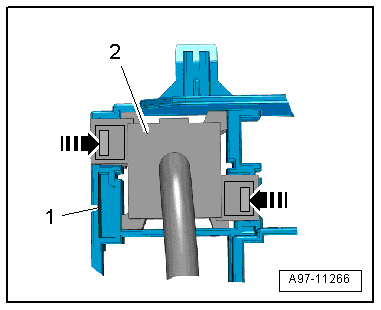
- Slide the locking lever -2- into the "open" position in direction of -arrow-.
- Press the release -1- and push the mount -3- toward the rear.
Installing
Install in reverse order of removal. Note the following:
- Slide the locking lever -1- onto the mount into the "closed" position.
- Both markings -arrows- must align.
Door Cut-Off Connector, Disconnecting
Front Door Cut-Off Connector, Disconnecting
Procedure
- Open the door.
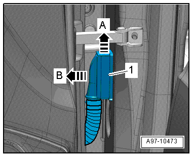
- Release the connector catch in the direction of -arrow A- and remove the door cut-off connector -1- toward the outside in direction of -arrow B-.
Rear Door Cut-Off Connector, Disconnecting
Procedure
- Open the front door.
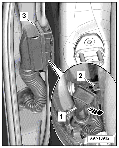
- Remove the retainer in direction of -arrow A-.
- Pull the door cut-off connector -1- as far as possible toward the outside in direction of -arrow B-.
- Install the retainer -3-.
- Swivel the door cut-off connector -1- forward -arrow- and disconnect the connector -2-.
Left A-Pillar Connector Station, Removing and Installing
Removing
- With the ignition switched off, disconnect the ground cable from the battery. Refer to → Chapter "Battery, Disconnecting and Connecting".
- Remove the front sill panel. Refer to → Body Interior; Rep. Gr.70; Passenger Compartment Trim; Sill Panel Strip, Removing and Installing.
- Push the retainer in direction of -arrow- and disengage the connector station -3- from the A-pillar.
- Unclip the fuse panel from the connector station.
- Remove the mount -2- for the 46-Pin Connector -T46b-. Refer to → Chapter "CAN Cut-Off Connector Mount, Removing and Installing".
Note
Ignore -item 1-.
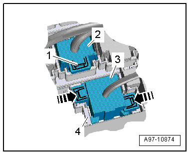
- Open the clip and remove the auxiliary fuse panel -2-.
- Release the clips in direction of -arrows- and remove the relay -1- and the control modules from the relay carriers.
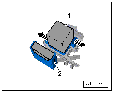
- Release the retaining clips in direction of -arrows- and press the relay carrier -3- back and out of the bracket -4-.
- Open the clip -2- and remove the connector -1-.
Note
Check the exact connector assignment in the current wiring diagram → Wiring diagrams, Troubleshooting & Component locations.
Installing
Install in reverse order of removal. Note the following:
- Connect the battery. Required steps: vehicles without high voltage system. Refer to vehicles with high voltage system.
Right A-Pillar Connector Station, Removing and Installing
Removing
- With the ignition switched off, disconnect the ground cable from the battery. Refer to → Chapter "Battery, Disconnecting and Connecting".
- Remove the front sill panel. Refer to → Body Interior; Rep. Gr.70; Passenger Compartment Trim; Sill Panel Strip, Removing and Installing.
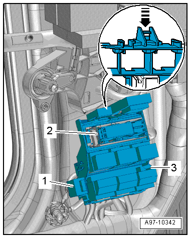
- Push the retainer in direction of -arrow- and disengage the connector station -1- from the A-pillar.
- Unclip the fuse panel -2- from the connector station.
- Release the retainers -arrows- and remove the relay carrier -2- from the connector station -1- to the rear.
Note
Check the exact connector assignment in the current wiring diagram → Wiring diagrams, Troubleshooting & Component locations.
Installing
Install in reverse order of removal. Note the following:
- Connect the battery. Required steps: vehicles without high voltage system. Refer to vehicles with high voltage system.
Special Tools
Special tools and workshop equipment required
- Fiber-Optic Repair Set - Connector Protective Caps -VAS6223/9- from Fiber-Optic Repair Set -VAS6223B-
Revision History
DRUCK NUMBER: A005A000321