Audi A6 Typ 4G: Sensors
Overview - Front Axle Speed Sensor
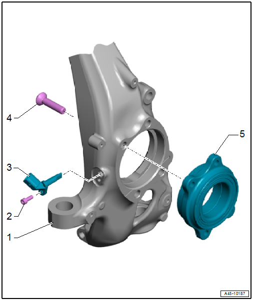
1 - Wheel Bearing Housing
2 - Bolt
- 9 Nm
3 - Speed Sensor
- Right Front ABS Wheel Speed Sensor -G45-/Left Front ABS Wheel Speed Sensor -G47-
- Removing and installing. Refer to → Chapter "Right/Left Front ABS Wheel Speed Sensor -G45-/-G47-, Removing and Installing".
4 - Bolt
- Tightening specification. Refer to → Suspension, Wheels, Steering; Rep. Gr.40; Wheel Bearing; Overview - Wheel Bearing.
5 - Wheel Bearing Unit
- The ABS sensor ring is integrated in the wheel bearing unit
Overview - Rear Axle Speed Sensor
Overview - Rear Axle Speed Sensor, FWD Vehicles
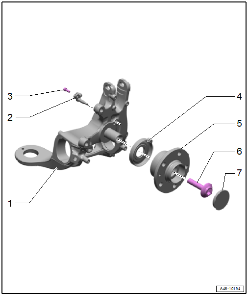
1 - Wheel Bearing Housing
2 - Speed Sensor
- Right Rear ABS Wheel Speed Sensor -G44-/Left Rear ABS Wheel Speed Sensor -G46-
- Removing and installing. Refer to → Chapter "Right/Left Rear ABS Wheel Speed Sensor -G44-/-G46-, Removing and Installing".
3 - Bolt
- 9 Nm
4 - Front Seal
5 - Wheel Bearing Unit
- The ABS sensor ring is integrated in the wheel bearing unit
6 - Bolt
- Tightening specification. Refer to → Suspension, Wheels, Steering; Rep. Gr.42; Wheel Bearing and Trailing Arm; Overview - Wheel Bearing.
7 - Dust Cap
Overview - Rear Axle Speed Sensor, AWD Vehicles
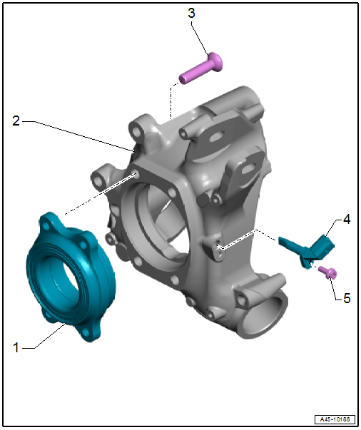
1 - Wheel Bearing Unit
- The ABS sensor ring is integrated in the wheel bearing unit
2 - Wheel Bearing Housing
3 - Bolt
- Tightening specification. Refer to → Suspension, Wheels, Steering; Rep. Gr.42; Wheel Bearing and Trailing Arm; Overview - Wheel Bearing.
4 - Speed Sensor
- Right Rear ABS Wheel Speed Sensor -G44-/Left Rear ABS Wheel Speed Sensor -G46-
- Removing and installing. Refer to → Chapter "Right/Left Rear ABS Wheel Speed Sensor -G44-/-G46-, Removing and Installing".
5 - Bolt
- 9 Nm
Brake Lamp Switch, Removing and Installing
Special tools and workshop equipment required
- Release Tool for Brake Light Switch -T40168A-
Component location: on the brake pedal
Removing
- Remove the driver side footwell vent. Refer to → Heating, Ventilation and Air Conditioning; Rep. Gr.87; Air Guide; Driver Side Footwell Vent, Removing and Installing.
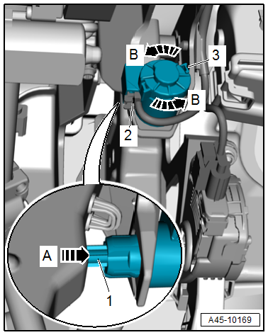
- Disconnect the connector -2- from the Brake Lamp Switch -F-.
- Press the brake lamp switch piston -1- in completely with a finger -arrow A-.
- To release the brake lamp switch, turn the rotating piece -3-, with the piston pressed, counter-clockwise -B arrows- until it stops
- Disengage the piston from the released brake lamp switch.
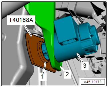
- Insert the Release Tool for Brake Light Switch -T40168A- between the brake lamp switch piston and the brake pedal, as shown in the illustration.
- The tool taper -1- must face the driver seat The opening on the tool must align with the projection on the brake lamp switch.
- Press the Release Tool for Brake Light Switch -T40168A- against the Brake Lamp Switch. The three tabs on the brake lamp switch unlock at the same time.
- Pull the Brake Lamp Switch -F--item 3- out of the mount -2-.
Installing
Install in reverse order of removal and note the following:
- The brake push rod must be engaged with the brake pedal.
- When installing the switch the brake pedal must not be operated.
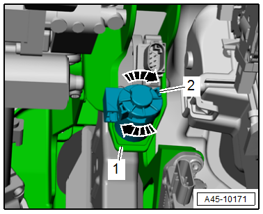
- Insert the Brake Lamp Switch -F- into the mount -1- on the brake pedal.
- The Brake Lamp Switch -F- must audibly engage with all three tabs.
- Do not turn the Brake Lamp Switch -F- once it is inside the mount on the brake pedal.
- The piston aligns itself automatically when inserting.
- To attach the brake lamp switch, turn the rotating piece -2- clockwise until it stops -arrows-.
Further installation is performed in reverse order of removal, while noting the following:
- Install the driver side footwell vent. Refer to → Heating, Ventilation and Air Conditioning; Rep. Gr.87; Air Guide; Driver Side Footwell Vent, Removing and Installing.
 Note
Note
Make sure the brake lamp switch is working correctly before driving the vehicle for the first time.
Brake Pedal Position Sensor, Removing and Installing
Note
Vehicles with a high-voltage system additionally have a Brake Pedal Position Sensor -G100-.
Removing
- Remove the driver side footwell vent. Refer to → Heating, Ventilation and Air Conditioning; Rep. Gr.87; Air Guide; Driver Side Footwell Vent, Removing and Installing.
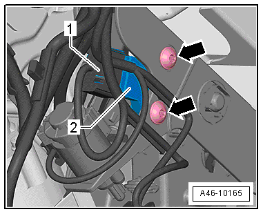
- Disconnect the connector -1-.
- Remove the bolts -arrows- and the Brake Pedal Position Sensor -G100--item 2-.
Installing
Install in reverse order of removal and note the following:
- Install the driver side footwell vent. Refer to → Heating, Ventilation and Air Conditioning; Rep. Gr.87; Air Guide; Driver Side Footwell Vent, Removing and Installing.
Sensor Electronics Control Module, Removing and Installing
Special tools and workshop equipment required
- Torque Wrench 1331 5-50Nm -VAG1331-
Note
If the Sensor Electronics Control Module -J849- is being replaced, select the "Replace" function for the Sensor Electronics Control Module -J849- on the Vehicle Diagnostic Tester in Guided Functions.
Removing
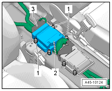
The Sensor Electronics Control Module -J849- is installed under the center console cover.
- Remove the center console cover. Refer to → Body Interior; Rep. Gr.68; Center Console; Overview - Center Console.
- Disconnect the connector -3-.
- Remove all four nuts -1-.
- Remove the Sensor Electronics Control Module -J849--2-.
Installing
Install in reverse order of removal and note the following:
 Caution
Risk of destroying the Sensor Electronics Control Module -J849-.
Protect the Sensor Electronics Control Module -J849- from bumps or impact: A Sensor Electronics Control Module -J849- that has fallen to the ground can no longer be used.
- Mount the Sensor Electronics Control Module -J849- on the four bolts.
Note
Make sure it is in the correct installation position. The connector faces the direction of travel.
- Ensure a stress-free seating on the mounting.
Note
To install the Sensor Electronics Control Module -J849--item 2- free of tension, install all the nuts -1- loosely and then tighten them diagonally.
- Install the center console cover. Refer to → Body Interior; Rep. Gr.68; Center Console; Overview - Center Console.
- If the Sensor Electronics Control Module -J849- is being replaced, select the "Replace" function for the Sensor Electronics Control Module -J849- on the Vehicle Diagnostic Tester in Guided Functions.
Right/Left Front ABS Wheel Speed Sensor -G45-/-G47-, Removing and Installing
Special tools and workshop equipment required
- Torque Wrench 1332 40-200Nm -VAG1332-
- Grease -G 000 650-
Note
The sensor ring/rotor is installed in the respective wheel bearing unit and cannot be replaced.
Removing
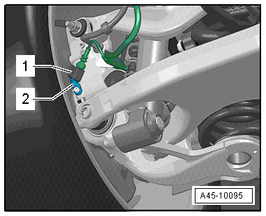
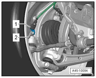
- Release and disconnect the connector on the speed sensor -1-.
- Remove the bolt -2-.
- Remove the speed sensor from the wheel bearing housing.
Installing
Install in reverse order of removal and note the following:
- Before inserting speed sensor, clean hole inner surface and coat speed sensor all-round with Grease -G 000 650-.
- Insert the speed sensor and tighten.
- After installing, turn the steering all the way to the left and right, to make sure the speed sensor wiring has sufficient clearance.
Right/Left Rear ABS Wheel Speed Sensor -G44-/-G46-, Removing and Installing
Special tools and workshop equipment required
- Torque Wrench 1332 40-200Nm -VAG1332-
- Grease -G 000 650-
Note
The sensor ring/rotor is installed in the respective wheel bearing unit and cannot be replaced.
Removing
FWD Vehicles:
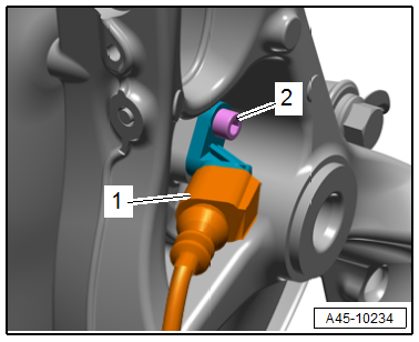
- Release and disconnect the connector on the speed sensor -1-.
- Remove the bolt -2-.
- Remove the speed sensor from the wheel bearing housing.
AWD vehicles:
- Release and disconnect the connector on the speed sensor -1-.
- Remove the bolt -2-.
- Remove the speed sensor from the wheel bearing housing.
Installing
Install in reverse order of removal and note the following:
- Before inserting speed sensor, clean hole inner surface and coat speed sensor all-round with Grease -G 000 650-.
- Insert the speed sensor and tighten.