Audi A6 Typ 4G: Driver Assistance Systems Front Camera
Overview - Driver Assistance Systems Front Camera
Overview - Driver Assistance Systems Front Camera
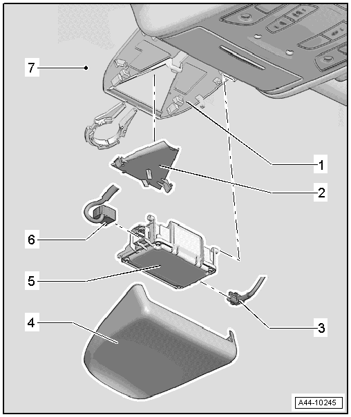
1 - Retaining Plate
- With Camera Control Module -J852- heated windshield
- Cannot be separated from the windshield
2 - Lens Shade
- Removing and installing. Refer to → Chapter "Driver Assistance Systems Front Camera, Removing and Installing".
3 - Connector
4 - Cover Trim
5 - Camera Control Module -J852-
- Removing and installing. Refer to → Chapter "Driver Assistance Systems Front Camera, Removing and Installing".
6 - Connector
7 - Windshield
Overview - Driver Assistance Systems Front Camera, Image Processing Control Module -J851-
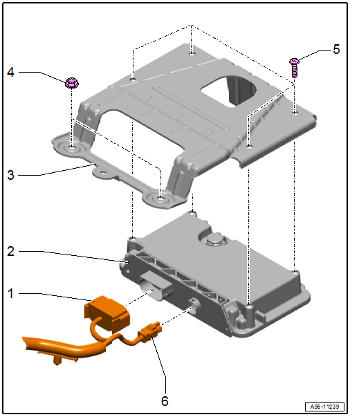
1 - Connector
2 - Image Processing Control Module -J851-
- Removing and installing. Refer to → Chapter "Image Processing Control Module -J851-, Removing and Installing".
3 - Bracket
- For Image Processing Control Module -J851-
4 - Nut
- 2.5 Nm
- Quantity: 4
5 - Screw
- 8 Nm
- Quantity: 4
6 - Antenna Wire
Driver Assistance Systems Front Camera, Removing and Installing
Special tools and workshop equipment required
- Backrest Panel Tool -3370-
 Note
Note
If replacing the control module, select the "Replace Control Module" function for the respective control module using the Vehicle Diagnostic Tester.
Removing
- Release the cover plate -1- for the Camera Control Module -J852- from the retaining plate in the direction of -arrow A- with the Backrest Panel Tool -3370--2- alternating from the right and the left and remove downward in the direction of -arrow B-.
- Free up the electrical wire if necessary.
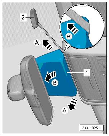
- Push the locking latches -2 and 4- upward.
Note
Carefully push the locking latches upward only until the Camera Control Module -J852- can be guided past.
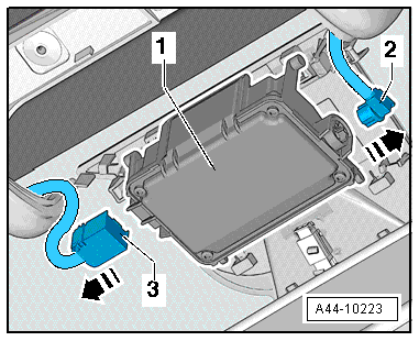
- Remove the Camera Control Module -J852--1- to the rear, parallel to the retaining plate -5-, in the direction of -arrow 3- from the mounts -arrow- from the retaining plate -5-.
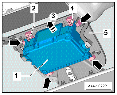
- Remove the connectors -2 and 3- and remove the Camera Control Module -J852--1-.
Lens Shade, Removing
- Press the clamps in direction of -arrows- together and remove the lens forward from the bracket.
Installing
Install in reverse order of removal. Note the following:
Note
The camera vision range on the inside of the windshield must not be fogged up or dirty.
- Clean the lens on the windshield with Cleaning Solution -D 009 401 04-.
- Calibrate the driver assistance systems front camera. Refer to → Suspension, Wheels, Steering; Rep. Gr.44; Driver Assistance Systems Front Camera; Driver Assistance Systems Front Camera, Calibrating.
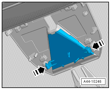
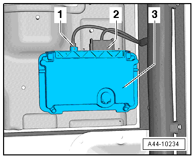
Image Processing Control Module -J851-, Removing and Installing
Note
If replacing the control module, select the "Replace Control Module" function for the respective control module using the Vehicle Diagnostic Tester.
Removing
The Image Processing Control Module -J851- is located in the front passenger seat footwell.
- Remove the front sill panel. Refer to → Body Interior; Rep. Gr.70; Passenger Compartment Trim; Sill Panel Strip, Removing and Installing.
- Remove the floor mat.
- Remove the foot rest. Refer to → Body Interior; Rep. Gr.70; Passenger Compartment Trim; Foot Rest, Removing and Installing.
- Loosen the front passenger seat and push rearward with the wires still attached. Refer to → Body Interior; Rep. Gr.72; Front Seats; Front Seat, Removing and Installing.
- Disengage the carpet and push aside.
- Remove the nuts -arrows-.
- Remove the bolts -1 to 4- and remove the bracket -5- from the image processing control module.
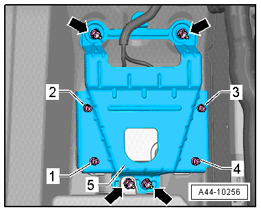
- Disconnect the connector -2- and antenna wire -1-.
- Remove the image processing control module -3- from the front passenger footwell.
Installing
Install in reverse order of removal.