Audi A6 Typ 4G: Socket Illumination Bulb -L42-, Removing and Installing
Socket Illumination Bulb -L42- Removing and Installing, 12 V Socket -U5-
Special tools and workshop equipment required
Removing
- Remove the center console storage compartment. Refer to → Body Interior; Rep. Gr.68; Center Console; Overview - Center Console.
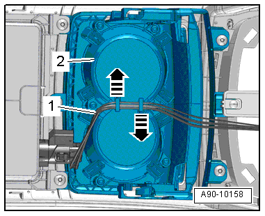
- Free up the electric wire -1- on the cup holder -2- in direction of -arrows-.
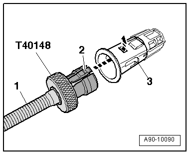
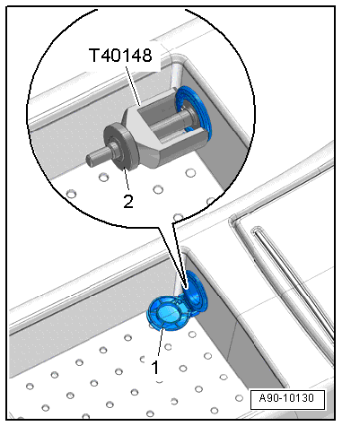
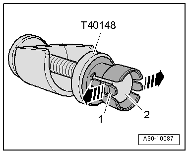
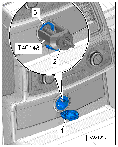
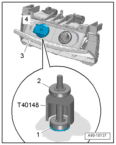
- The release tabs -2- on the Calibration Tool - Lane Change Calibration Tool -VAS6350/4- must engage in the openings on the 12 V socket -3- in direction of -arrow- and the threaded pin -1- must slide down as far as the stop.
- Open the cover -1- on the 12 V socket and hold it in this position.
- Disconnect the connector.
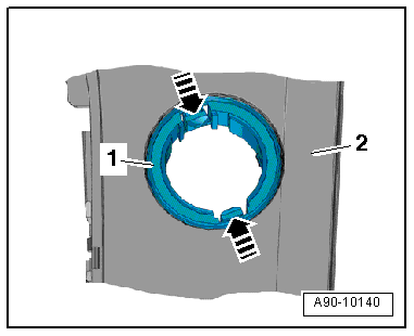
- Release the retaining tabs in direction of -arrows-.
- Remove the illumination ring -1- with the Socket Illumination Bulb -L42- from the storage compartment -2- in the inside the center console.
Installing
Install in reverse order of removal. Note the following:
- Slide the piston down and hold it in place.
Socket Illumination Bulb -L42- Removing and Installing, 12 V Socket 2 -U18-
Special tools and workshop equipment required
Removing
- The release tabs -2- on the Calibration Tool - Lane Change Calibration Tool -VAS6350/4- must engage in the openings on the 12 V socket -3- in direction of -arrow- and the threaded pin -1- must slide down as far as the stop.
- Open the cover -1- on the 12 V socket and hold it in this position.
- Release the retaining tabs in direction of -arrows-.
- Remove the 12 V socket and illumination ring -1- from the trim -2-.
- Guide the electric wire through the mount in direction of -arrow- and disconnect it.
Installing
Install in reverse order of removal. Note the following:
- Slide the piston down and hold it in place.
Socket Illumination Bulb -L42- Removing and Installing, 12 V Socket 4 -U20-
Removing
- The release tabs -2- on the Calibration Tool - Lane Change Calibration Tool -VAS6350/4- must engage in the openings on the 12 V socket -3- in direction of -arrow- and the threaded pin -1- must slide down as far as the stop.
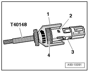
- Open the cover -3- for the 12 V socket.
- Open the cover -4- on the 12 V socket and hold it in this position.
- Release the retaining tabs in direction of -arrows-.
- Remove the 12 V socket and illumination ring -1- from the mount -2-.
- Guide the wire through the mount.
Installing
Install in reverse order of removal. Note the following:
- Slide the piston down and hold it in place.
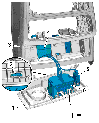
Converter with Socket, 12 V-230 V -U13-, Removing and Installing
Converter with Socket, 12 V-230 V -U13-, Removing and Installing, Market-Specific
Removing
- Remove the center console rear cover. Refer to → Body Interior; Rep. Gr.68; Center Console; Overview - Center Console.
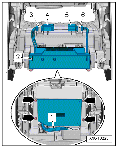
- Release the tabs -3 and 6- and free up the connectors -4 and 5- on the mount.
- Remove the bolts -arrows-.
- Remove the Converter with Socket, 12 V-230 V -U13--item 2- from the mount.
- Free up the wiring harness -1- on the mount.
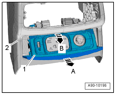
- Remove the mount -1- from the rear cover -2--arrow B- and then disengage it on the pivot bearing in direction of -arrow A-.
- Release the tabs -3 and 4- and at the same time remove the mounts -1 and 6-.
- Remove the cover -2- from the mount -5- in direction of -arrow-.
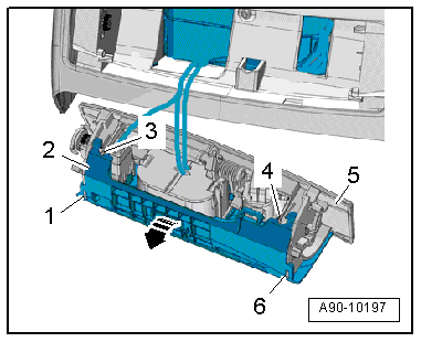
- Free up the USB-charger -5-.
- Release the tabs -2- and the open the tabs -7-.
- Remove the 230-Volt-socket -6- from the cover -1-.
- Remove the 230-Volt-socket and the USB-charger through the opening in the rear cover -3-.
- Remove the converter -4- with the 230-Volt-socket and the USB-charger.
Installing
Install in reverse order of removal.
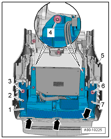
12V and 230V Converter with Socket -U13- Bracket, Removing and Installing, Market Specific
Removing
- Remove the center console rear cover. Refer to → Body Interior; Rep. Gr.68; Center Console; Overview - Center Console.
- Remove the bolts -3, 4 and 6-.
- Guide out the bracket -1- from the centering pins -2 and 7- from the rear cover -5--arrows- and remove them downward.
- If the bracket is replaced:
- Remove the converter with socket, 12 V-230 V. Refer to → Chapter "Converter with Socket, 12 V-230 V -U13-, Removing and Installing, Market-Specific".
Installing
Install in reverse order of removal.
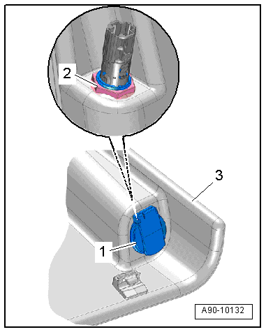
12 V Socket 3 -U19-, Removing and Installing
Removing
- Remove the luggage compartment side trim panel cover.
- Remove the nut -2-.
- Remove the 12 V socket -1- from the luggage compartment trim panel -3-.
Installing
Install in reverse order of removal.
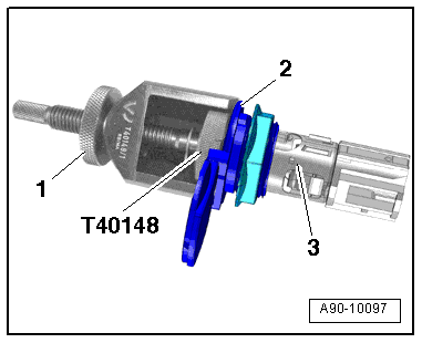
12 V Socket 3 -U19-, Replacing
Special tools and workshop equipment required
Removing
- The release tabs -2- on the Calibration Tool - Lane Change Calibration Tool -VAS6350/4- must engage in the 12 V socket openings -3- in direction of -arrow- and the threaded pin -1- must slide down as far as the stop.
- Open the mount cover -2- and hold it in that position.
- Remove the 12 V socket from the luggage compartment trim panel.
- Disconnect the connector.
Installing
Install in reverse order of removal. Note the following:
- Slide the piston down and hold it in place.
Special Tools
Special tools and workshop equipment required
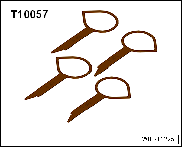
- Radio Removal Tool -T10057-
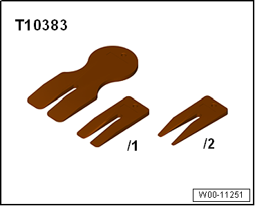
- Wedge Set -T10383-
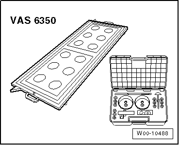
- Calibration Tool -VAS6350-
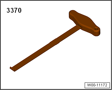
- Backrest Panel Tool -3370-
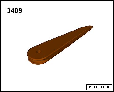
- Trim Removal Wedge -3409-