Audi A6 Typ 4G: Headlamp Power Output Stage, Removing and Installing
Right and Left LED Headlamp Power Output Module 1 -A27-/-A31-, Removing and Installing, through MY 2014
Removing
- Remove the front wheel housing liner. Refer to → Body Exterior; Rep. Gr.66; Wheel Housing Liner; Front Wheel Housing Liner, Removing and Installing.
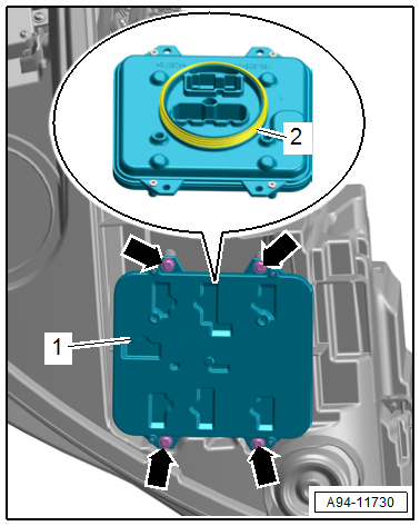
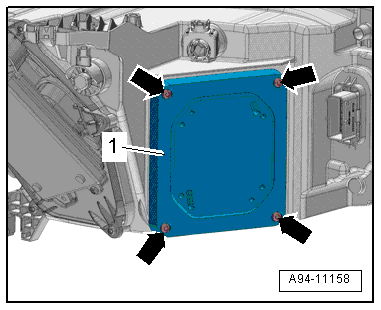
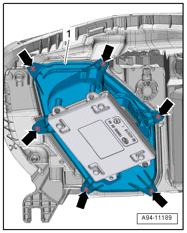
- Remove the bolts -arrows-.
- Remove the power output stage -2-.
Installing
Install in reverse order of removal. Note the following:
- Check the seal -1- for damage.
Right/Left LED Headlamp Power Output Module 1-A27-/-A31-, Removing and Installing, from MY 2015
Removing
- On the right: remove the air filter housing. Refer to → 6-Cylinder TDI Common Rail 3.0L 4V Engine; Rep. Gr.23; Air Filter; Air Filter Housing, Removing and Installing or → Rep. Gr.24; Air Filter; Air Filter Housing, Removing and Installing.
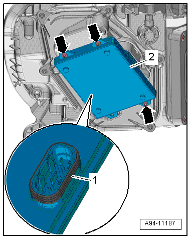
- Remove the bolts -arrows-.
- Remove the power output stage -2-.
Installing
Install in reverse order of removal. Note the following:
- Check the seal -1- for damage.
Right and Left LED Headlamp Power Output Module 2 -A28-/-A32-, Removing and Installing, through MY 2014
Removing
- Remove the headlamp housing. Refer to → Chapter "Headlamp Housing, Removing and Installing, HID Headlamp and LED Headlamp through MY 2014".
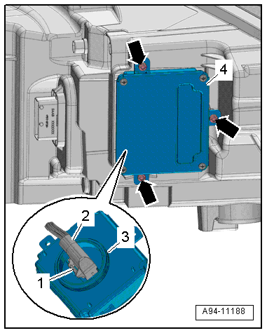
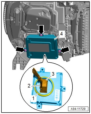
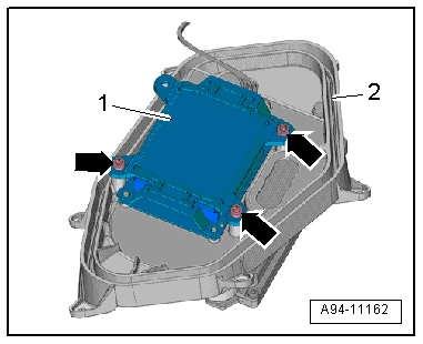
- Remove the bolts -arrows-.
- Remove the power output stage -4-.
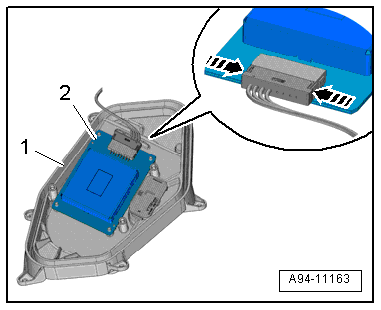
- Press the release button -1- and disconnect the connector -2-.
- Remove the power output stage.
Installing
Install in reverse order of removal. Note the following:
- Check the seal -3- for damage.
Right/Left LED Headlamp Power Output Module 2 -A28-/-A32-, Removing and Installing, from MY 2015
Removing
- Loosen the front wheel housing liner and move it to the side. Refer to → Body Exterior; Rep. Gr.66; Wheel Housing Liner; Front Wheel Housing Liner, Removing and Installing.
- Remove the bolts -arrows-.
- Remove the power output stage -4-.
- Press the release -2- button and disconnect the connector -3-.
- Remove the power output stage.
Installing
Install in reverse order of removal. Note the following:
- Check the seal -1- for damage.
Left/Right LED Headlamp Power Output Module 3 -A29-/- A33-, Removing and Installing
Special tools and workshop equipment required
- Spark Plug Pliers -VAG1922-
 Caution
Danger of causing damage to the vehicle electronics.
- Requirement: Make sure nothing, especially metal or other light weight particles, can get into the headlamp housing.
- Make sure also no oil, grease, silicone or other such materials can get into an open headlamp, otherwise they can turn into steam and fog up the headlamp.
- Touching electronic circuits with bare hands can lead to migration.
- ESD (electrostatic discharge) protection: Always follow standard DIN EN 613-40-5-1 when handling.
- Do not use any components or electronics that have fallen down.
- ESD Work Surface -VAS6613-. Refer to → Electrical System General Information; Rep. Gr.97; ESD Work Surface VAS6613.
 DANGER!
Damaged high voltage components may produce dangerously high voltage.
Note the following when working near high voltage components and cables:
- Do not use tools that have sharp edges, that are used for cutting or shaping, or that generate heat, such as welding, soldering, hot air or thermal adhesive equipment.
- Inspect the high voltage components in the area where the work will be performed before starting the procedure.
- Perform a visual inspection of the Electric Drive Power and Control Electronics -JX1-, the Electro-Drive Drive Motor -V141-, the Electrical A/C Compressor -V470- and the high voltage cables when working inside the engine compartment.
- Perform a visual inspection of the high voltage cables and the covers when working on the floor panel.
- Perform a visual inspection of the high voltage cables and the electro-box with the High Voltage System Maintenance Connector -TW- when working in the rear of the vehicle.
- Perform a visual inspection of all of the potential equalization cables.
- Note the following when performing the visual inspection:
- None of the components may display any exterior damage.
- The high voltage cable insulation and the potential equalization cables may not be damaged.
- The high voltage cables may not be deformed in any way.
- Each high voltage component muss be labeled with a red warning label.
Removing
- On the right: remove the air filter housing. Refer to → 6-Cylinder TDI Common Rail 3.0L 4V Engine; Rep. Gr.23; Air Filter; Air Filter Housing, Removing and Installing or → Rep. Gr.24; Air Filter; Air Filter Housing, Removing and Installing.
- Left: If equipped, remove the resonator with air filter. Refer to → Rep. Gr.26; Secondary Air Injection System; Secondary Air Injection Pump Motor V101, Removing and Installing.
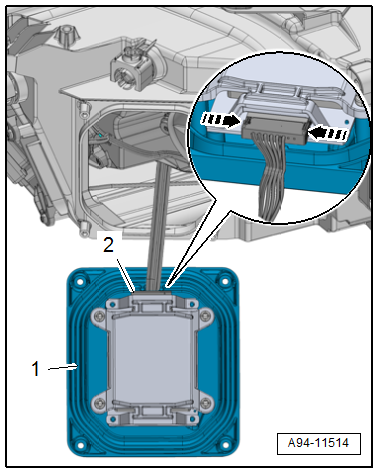
- Remove the bolts -arrows-.
- Remove the housing cover -1-.
- Disconnect the connector -2- on the power output stage by pressing the release buttons -arrows- using the Spark Plug Pliers -VAG1922-.
- Remove the housing cover -1-.
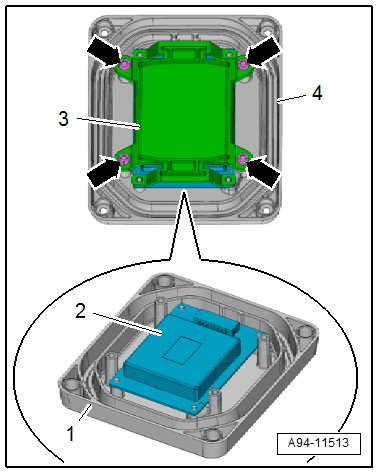
- Remove the screws -arrows- and the frame -3- from the housing cover -4-.
- Remove the power output stage -2- from the housing cover -1-.
Installing
Install in reverse order of removal. Note the following:
- Close the housing cover and tighten the bolts.
Left/Right LED Headlamp Power Output Module 4 -A34-/-A30-, Removing and Installing
Caution
Danger of causing damage to the vehicle electronics.
- Requirement: Make sure nothing, especially metal or other light weight particles, can get into the headlamp housing.
- Make sure also no oil, grease, silicone or other such materials can get into an open headlamp, otherwise they can turn into steam and fog up the headlamp.
- Touching electronic circuits with bare hands can lead to migration.
- ESD (electrostatic discharge) protection: Always follow standard DIN EN 613-40-5-1 when handling.
- Do not use any components or electronics that have fallen down.
- ESD Work Surface -VAS6613-. Refer to → Electrical System General Information; Rep. Gr.97; ESD Work Surface VAS6613.
Removing
- Remove the front wheel housing liner. Refer to → Body Exterior; Rep. Gr.66; Wheel Housing Liner; Front Wheel Housing Liner, Removing and Installing.
- Remove the bolts -arrows-.
- Remove the housing cover -1-.
- Remove the screws -arrows- and the frame -1- from the housing cover -2-.
- Remove the power output stage -2- from the housing cover -1-.
- Press the releases -arrows- and disconnect the connector.
Installing
Install in reverse order of removal. Note the following:
- Close the housing cover and tighten the bolts.
Left and Right Matrix Headlamp Power Output Stage -A44-/-A45-, Removing and Installing
Removing
- Remove the headlamp housing. Refer to → Chapter "Headlamp Housing, Removing and Installing, HID Headlamp and LED Headlamp from MY 2015".
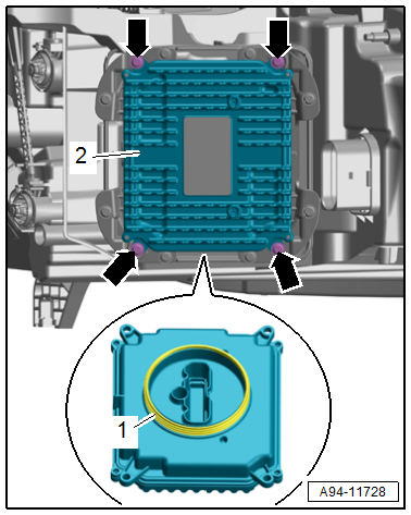
- Remove the bolts -arrows-.
- Remove the power output stage -1-.
Installing
Install in reverse order of removal. Note the following:
- Make sure the seal -2- between the power output stage and the headlamp is not damaged.