Audi A6 Typ 4G: Microphone Unit in Front Roof Module -R164-, Removing and Installing
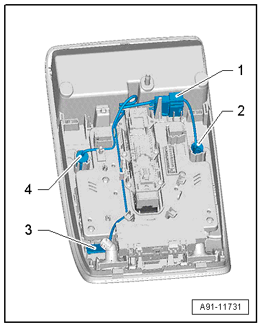
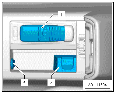
The Microphone Unit In Front Roof Module -R164- located in the Front Interior Lamp -W1- can only be replaced as a complete unit.
Removing
- Turn off the ignition and all electrical consumers and remove the ignition key.
- Remove the Front Interior Lamp -W1-. Refer to → Electrical Equipment; Rep. Gr.96; Controls; Front Interior Lamp/Reading Lamp, Removing and Installing.
- Unclip and disconnect the connector -1- from the bracket in the Front Interior Lamp -W1-.
- Pry each microphone -2-, -3- and -4- out of the retainer.
Installing
- Install in reverse order of removal.
Cellular Telephone Amplifier -R86-, Removing and Installing
Cellular Telephone Amplifier -R86-, Removing and Installing, through MY 2014
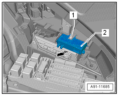
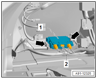
The Cellular Telephone Amplifier -R86--1- is located behind the right luggage compartment trim panel.
Removing
- Turn off the ignition and all electrical consumers and remove the ignition key.
- Open the right storage compartment in the luggage compartment.
- Release and disconnect the connectors from the Cellular Telephone Amplifier -R86--2-.
- Push the tab -1- upward and remove the Cellular Telephone Amplifier -R86--2- from the bracket in the direction of the -arrow-.
Installing
- Install in reverse order of removal.
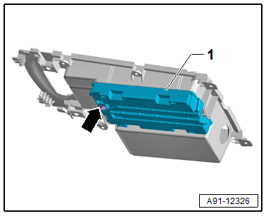
Cellular Telephone Amplifier -R86-, Removing and Installing, from MY 2015
The Cellular Telephone Amplifier -R86- is located behind the left luggage compartment trim panel.
Removing
- Turn off the ignition and all electrical consumers and remove the ignition key.
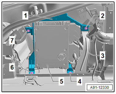
The bracket with the Digital Sound System Control Module -J525- must be removed first.
- Remove the left luggage compartment side trim panel. Refer to → Body Interior; Rep. Gr.70; Luggage Compartment Trim Panels; Luggage Compartment Side Trim Panel, Removing and Installing.
- Remove the nuts -4, 6 and 7- and the screw -2- on the bracket -1-.
- Remove the brace -3-.
- Pivot the Digital Sound System Control Module -J525--5- with the bracket -1- into the luggage compartment.
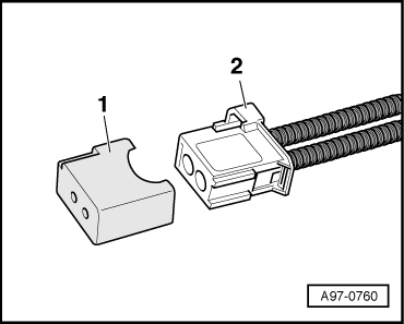
- Insert the Fiber-Optic Repair Set - Connector Protective Caps -VAS6223/9--1- onto the MOST Bus connector -2-.
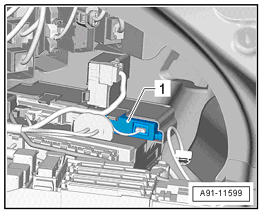
- Release and disconnect the connectors -2- from the Cellular Telephone Amplifier -R86--1-.
- Press the catches -arrows- and remove the Cellular Telephone Amplifier -R86--1- from the bracket.
Installing
- Install in reverse order of removal.
Telephone Baseplate -R126-, Removing and Installing
Front Telephone Baseplate -R126-, Removing and Installing, through MY 2014
The front Telephone Baseplate - R126--1- is located under the front center armrest
Removing
- Turn off the ignition and all electrical consumers and remove the ignition key.
- Remove the Telephone Handset -R37-/Cellular Telephone -R54-.
- Remove the center console storage compartment. Refer to → Body Interior; Rep. Gr.68; Center Console; Front Center Console Storage Compartment, Removing and Installing.
- Disconnect the connector.
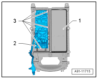
- Remove the screws -3-.
- Remove the Telephone Baseplate -R126--2- upward from the storage compartment -1-.
Installing
- Install in reverse order of removal.
Front Telephone Baseplate -R126-, Removing and Installing, from MY 2015
The front Telephone Baseplate - R126--1- is located under the front center armrest
Removing
- Turn off the ignition and all electrical consumers and remove the ignition key.
- Remove the Cellular Telephone -R54-.
- Remove the center console storage compartment. Refer to → Body Interior; Rep. Gr.68; Center Console; Front Center Console Storage Compartment, Removing and Installing.
- Release and disconnect the connectors.
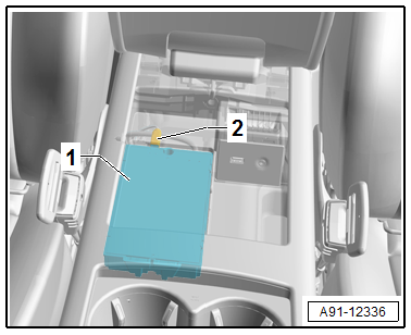
- Remove the screw -arrow-.
- Remove the Telephone Baseplate -R126--1- from the storage compartment.
Installing
- Install in reverse order of removal.