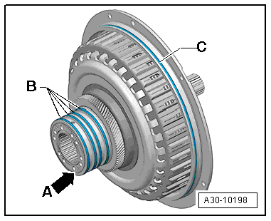
Audi A6 Typ 4G: Transmission Control
Overview - Transmission Control Module
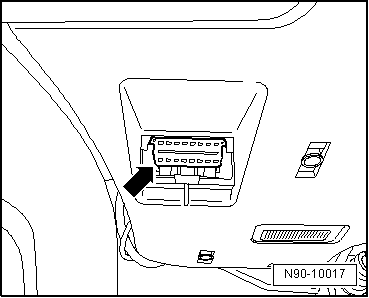
Diagnostic Connection
- Component location: The diagnostic connection for the Vehicle Diagnostic Tester in inside the footwell on the driver side.
- Before servicing the transmission, determine as best as possible the cause of the fault using the Vehicle Diagnostic Tester in Guided Fault Finding, Vehicle Self-Diagnosis and Test Instruments.
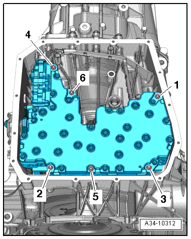
S tronic Transmission Mechatronic -J743-, valves, sensor and transmission input RPM sensor
- Component location: The S tronic Transmission Mechatronic -J743- is attached to the transmission housing at the bottom and covered by the transmission fluid pan.
 Note
Note
- The Mechatronic unit incorporates the hydraulic control, the transmission control module, the multifunction transmission range switch and the sensors and actuators as a complete synchronized unit.
- OBD checks all the components named.
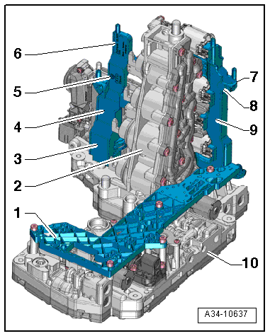
Gear selector, mechatronic temperature sensor in the overview
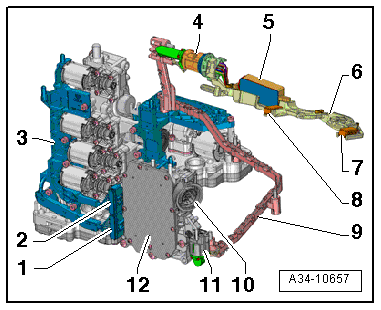
1 - Circuit Board 1
2 - Gear selector module
3 - Gear Position Distance Sensor 1 -G487- for gear position 2-R
4 - Gear Position Distance Sensor 2 -G488- for gear position 1-3
5 - Gear Position Distance Sensor 3 -G489- for gear position 7-5
6 - Gear Position Distance Sensor 4 -G490- for gear position 4-6
7 - Clutch Oil Temperature Sensor -G509-
8 - Transmission Input Speed Sensor 3 -G641- for the clutch input speed sensor
9 - Circuit Board 2
10 - Electro-hydraulic control module
The Circuit Board 1 and Circuit Board 2 can be individually removed and installed, description: → S tronic Transmission Internal Components; Rep. Gr.34; Mechatronic.
Mechatronic connectors and sensor module
Mechatronic connectors:
1 - Circuit board connector 1 on the transmission control module
2 - Circuit board connector 2 on the transmission control module
3 - Circuit Board 2
4 - Sensor Module connector at the wiring harness
5 - Drive Position Sensor -G676-
6 - Circuit board 3 in the sensor module
7 - Transmission Input Speed Sensor 1 -G632-
8 - Transmission Input Speed Sensor 2 -G612-
9 - Wiring harness with wiring channel
10 - Transmission control module to vehicle wiring harness
11 - Transmission control module at the sensor module
12 - Transmission control module
The components -4 through 8- are marked as sensor module.
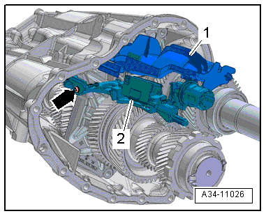
Sensor Module, with integrated transmitters and sensors Transmission Input Speed Sensor 2 -G612-,Transmission Input Speed Sensor 1 -G632-, Drive Position Sensor -G676- and circuit board 3
The Sensor Module-2- is installed in the transmission intermediate housing.
The following components are integrated on the sensor module:
- Drive Position Sensor -G676-
- Transmission Input Speed Sensor 1 -G632-
- Transmission Input Speed Sensor 2 -G612-
- Circuit board 3
- Sensor Module Removing and Installing, refer to → S tronic Transmission Internal Components; Rep. Gr.34; Transmission, Disassembling and Assembling; Overview - Transmission.
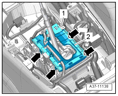
Selector Lever Sensor System Control Module -J587-
- Component location: The Selector Lever Sensor System Control Module -J587--2- is clipped to the gearshift mechanism function unit -arrows-.
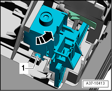
Shift Lock Solenoid -N110-
- Component location: The Shift Lock Solenoid -N110--1- is clipped to the selector mechanism.
Transmission Park Selector Switch -F305-
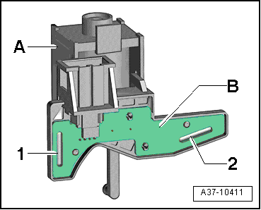
- Component location: The Transmission Park Selector Switch -F305-, which consists of two reed contacts -1- and -2-, is installed on the circuit board -B- on the Shift Lock Solenoid -N110--item A-.
 Note
Note
The Transmission Park Selector Switch -F305- can only be replaced together with the Shift Lock Solenoid -N110-.
Transmission Fluid Temperature Sensor 2 -G754-
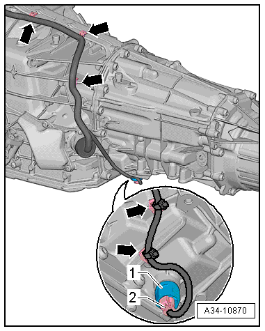
The 7-speed S tronic transmission 0B5 (S tronic) has an additional Transmission Fluid Temperature Sensor 2 -G754- to monitor the transmission fluid temperature of the wheel set on certain engine versions.
- Installed location: Depending on the date of manufacture, there are 2 different versions and component locations, either on the side or in place of the transmission fluid drain plug (Manual Transmission Fluid), refer to → S tronic Transmission Internal Components; Rep. Gr.34; Automatic Transmission Fluid.
Transmission Fluid Cooling Valve -N509-
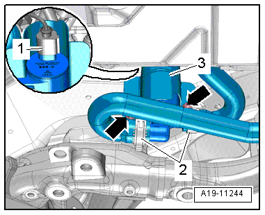
Component location: Depending on the engine types installed at the subframe or at the transmission housing. Removing and installing the Transmission Fluid Cooling Valve -N509-, refer to → Rep. Gr.19; Coolant Pump/Thermostat; Coolant Valve, Removing and Installing.
Transmission Range Display -Y6-
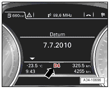
- Installed location: the Transmission Range Display -Y6--arrow- is integrated inside the instrument cluster.
 Note
Note
Replace the instrument cluster if one of the transmission range displays is faulty, refer to → Electrical Equipment; Rep. Gr.90; Instrument Cluster; Overview - Instrument Cluster.
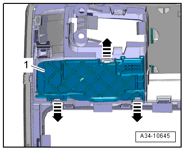
Selector Lever Transmission Range Position Display Unit -Y26-
- Component location: The Selector Lever Transmission Range Position Display Unit -Y26--item 1- is clipped inside the Multimedia System Control Head -E380-.
Removing and Installing, refer to → Electrical Equipment; Rep. Gr.96; Lamps; Selector Lever Transmission Range Position Display Unit Y26, Removing and Installing.
Kick Down Switch -F8-
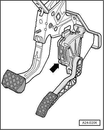
A programmed value from the Accelerator Pedal Position Sensor -G79- and Accelerator Pedal Position Sensor 2 -G185- (integrated in accelerator pedal module) are saved in the engine control module as a kick-down signal.
- Component location: The accelerator pedal position sensors are integrated inside the accelerator pedal module -arrow-.
 Note
Note
The accelerator pedal module must be replaced if the accelerator pedal position sensor is faulty, for the removal and Installation, refer to → Fuel Supply System; Rep. Gr.20; Accelerator Pedal Mechanism; Accelerator Pedal Position Sensors G79 / G185 , Removing and Installing.
Transmission Guided Functions
Special tools and workshop equipment required
- Vehicle Diagnostic Tester
Procedure:
- Vehicle Diagnostic Tester is connected.
- Perform "Guided Function" in Guided Functions, directory 02 - transmission electronics, functions on the Vehicle Diagnostic Tester.
Conditions:
- Follow the instructions on the Vehicle Diagnostic Tester exactly so that "Guided Functions" can be performed successfully.
Perform "Guided Functions" with a Vehicle Diagnostic Tester after performing the following:
1 - Replacing the selector mechanism function unit: 02 - basic setting (Repair Group 34).
2 - Working on the selector lever cable, adjusting the selector lever cable: 02 - basic setting (Repair Group 34).
3 - Replacing the S tronic Transmission Mechatronic -J743- and the Transmission Control Module -J217-: 02 - replace control module/Mechatronic (Repair Group 34).
4 - Replacing the dual clutch, replacing the transmission control module -J217-, repairing the transmission, replacing the components in the transmission: 02- Basic Setting (Rep.-Gr. 34).
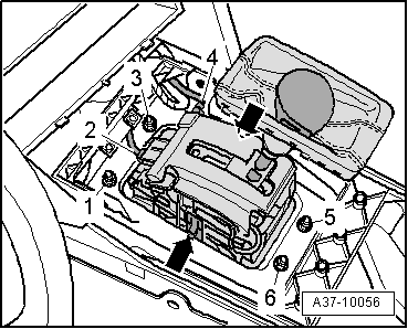
1. Replacing the shift mechanism function unit.
 Note
Note
Shift Mechanism Function Unit, Removing and Installing, refer to → Chapter "Selector Mechanism, Removing and Installing".
The following steps must be performed after completing this procedure:
- Under Guided Functions in the directory 02 - transmission electronics, select the basic setting (Repair Group 34)"Guided Function".
- Select calibrate drive position sensor -G676 and then follow the instructions given on the Vehicle Diagnostic Tester.
2. Assembly work on the selector lever cable when adjusting the cable.
 Note
Note
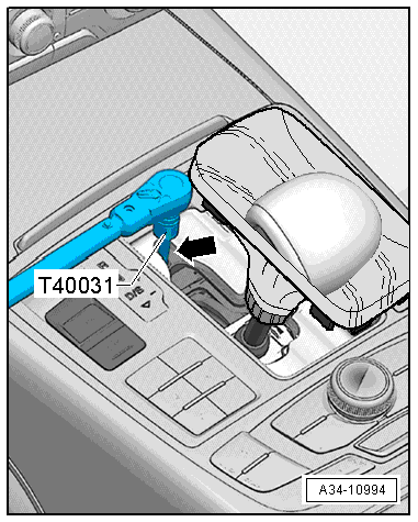
Adjust the selector lever cable, refer to → Chapter "Selector Lever Cable, Checking and Adjusting".
The following steps must be performed after completing this procedure:
- Under Guided Functions in the directory 02 - transmission electronics, select the basic setting (Repair Group 34)"Guided Function".
- Select calibrate drive position sensor -G676 and then follow the instructions given on the Vehicle Diagnostic Tester.
3. Replacing the S tronic Transmission Mechatronic -J743- and Transmission Control Module -J217-
 Note
Note
Direct Transmission Mechatronic -J743-, Removing and Installing, refer to → Chapter "Mechatronic, Removing and Installing".
The following steps must be performed after completing this procedure:
- Select Guided Functions in the directory 02 - transmission electronics and the replace control module/Mechatronic (Repair Group 34)"Guided Function" and then follow the instructions given on the Vehicle Diagnostic Tester.

4. Replacing the dual clutch.
 Note
Note
Dual clutch, removing and installing, refer to → S tronic Transmission Internal Components; Rep. Gr.30; Clutch; DSG Clutch, Removing or → S tronic Transmission Internal Components; Rep. Gr.30; Clutch; Dual Clutch, Installing.
The following steps must be performed after completing this procedure:
- Under Guided Functions in the directory 02 - transmission electronics, select the basic setting (Repair Group 34)"Guided Function".
- Select the basic setting adapt clutch slip points and then follow the instructions given on the Vehicle Diagnostic Tester.
