Audi A6 Typ 4G: Overview - Hood
Overview - Hood
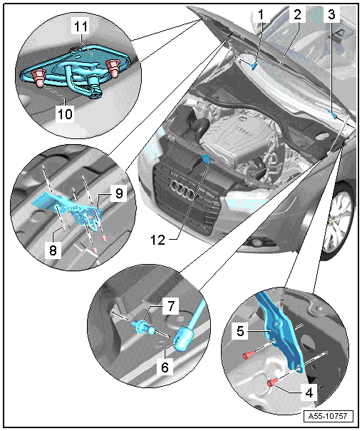
1 - Cover for the Right Hood Hinge
- Clipped onto the side
2 - Hood
- A second technician is needed to support and hold the hood during removal and installation.
- Removing
- Remove the gas-filled strut from the hood. Refer to → Chapter "Gas-Filled Strut, Removing and Installing".
- Remove the nuts -4- from the upper hood hinge.
- Remove the hood.
- Install in reverse order of removal.
 Note
Note
Perform a closing test. The hood must engage completely in the latches from a balanced position.
- Adjusting
- Center the hood between the fenders.
- Adjust the height of the hood over the lower part of the hood latch.
- Adjust the gap between the hood and the fenders using the stop buffers.
3 - Cover for the Left Hood Hinge
- Clipped onto the side
4 - Screws
- 21 Nm
5 - Hood Hinge
- For removal and installation, the hood must be removed or supported securely.
- Removing:
- Remove the gas-filled strut. Refer to → Chapter "Gas-Filled Strut, Removing and Installing"
- Remove the bolts -2- and nuts -4-.
- Install in reverse order of removal.
6 - Gas-Filled Strut
- Removing and installing. Refer to → Chapter "Gas-Filled Strut, Removing and Installing".
- The gas-filled strut tube is installed on the hood side.
7 - Ball Stud
- 10 Nm
8 - Nut
- 8 Nm
9 - Hook
- Removing and installing. Refer to → Chapter "Hood Hook, Removing and Installing"
10 - Nut
- 8 Nm
11 - Catch
- Removing and installing. Refer to → Chapter "Catch, Removing and Installing".
12 - Hook
- Removing and installing. Refer to → Chapter "Lock Carrier Hook, Removing and Installing".
Overview - Hood, Hood Latch
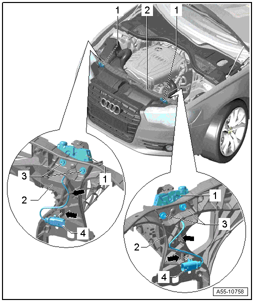
1 - Hood Latch
- Loosen the bumper cover at the top.
- Disconnect the cable from the hood latch.
- Disconnect the connector.
- Remove the bolts -1- and -2-.
Note
Move the hood latch in the oblong holes in the lock carrier to adjust the height of the hood.
2 - Lock Carrier
3 - Bolt
- 11 Nm
4 - Hood Latch Electric Wire
Overview - Hood, Gas-Filled Strut
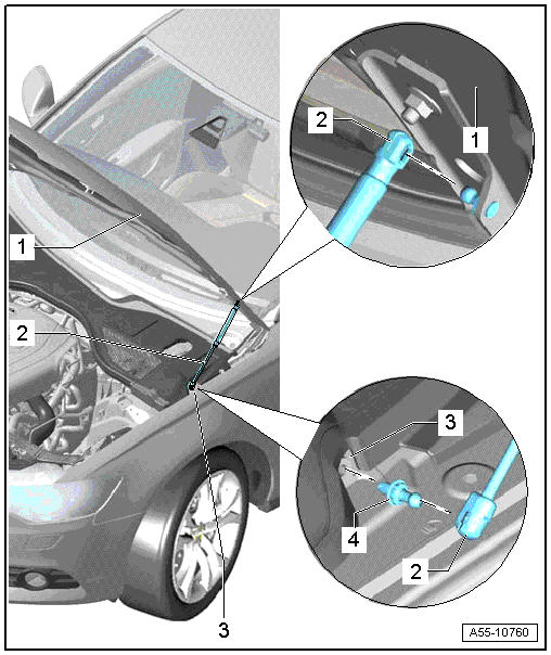
1 - Gas-Filled Strut
- Lift the locking spring slightly and pull the gas-filled strut off the ball stud.
Note
Ensure correct positioning during installation: the gas-filled strut tube must be attached on the lid side.
2 - Hood
3 - Suspension Strut Dome
4 - Ball Stud
- 21 Nm
Overview - Release Cable
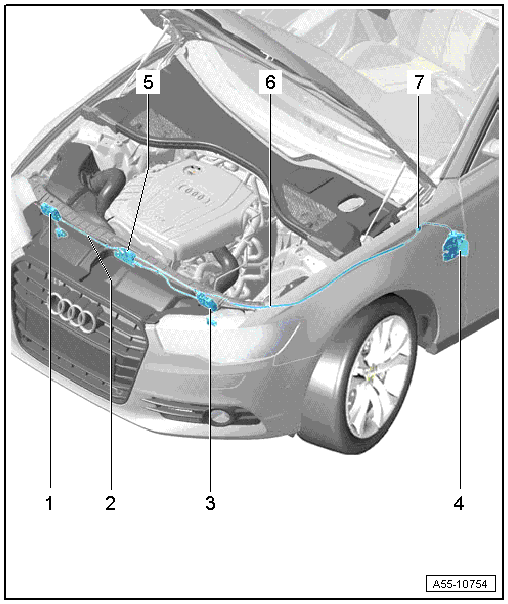
1 - Right Hood Latch
- Removing and installing. Refer to → Chapter "Overview - Hood, Hood Latch".
2 - Hood Latch Cable
- Removing:
- Disconnect the release cable at the coupling.
- Pull the release cable through to the engine compartment.
- Installing: install in reverse order of removal
- Adjust the hood latch point of release.
3 - Left Hood Latch
4 - Release Lever
- Disengage the release cable.
5 - Cable Coupling
- Disengage the release cable inside the passenger compartment before removing the lock carrier and when removing the operating lever.
6 - Hood Release Lever Cable
- Release cable to the operating lever in the vehicle interior.
7 - Grommet
- Make sure it fits correctly when installing it. The grommet must be pushed all the way into the bulkhead.
