Audi A6 Typ 4G: Peripheral Camera System, Calibrating
Calibration Tool -VAS6350- with Peripheral Camera Calibration Device -VAS6350/6-, Installing and Aligning
Special tools and workshop equipment required
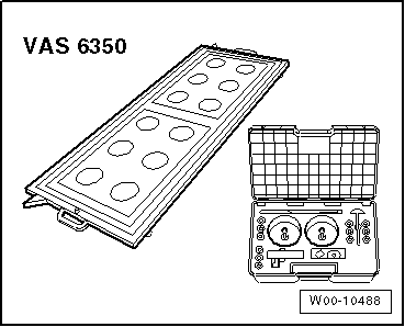
- Calibration Tool -VAS6350-
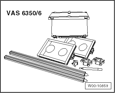
- Peripheral Camera Calibration Device -VAS6350/6-
- Vehicle Diagnostic Tester
After performing service work on the vehicle, it may be necessary to calibrate the peripheral camera system. In detail, this is the case after:
- Replacing one or more cameras
- Replace Peripheral Camera Control Module -J928- (all cameras need to be calibrated)
- Repair work on components in which a camera is installed or that influence the component location of the camera
- After suspension adjustments
- When adjusting the overlap range of the individual cameras
All cameras must be calibrated if the Peripheral Camera Control Module -J928- is replaced.
Calibration Requirements
- The camera lens must be clean. Cleaning
- Check the camera images on the Front Information Display Control Head -J685-. Replace the camera if the images are unclear because the camera has been damaged. Check the mount for the camera if the image is low.
- Make sure both exterior rearview mirrors are folded out.
- The vehicle must be standing on a firm and level surface.
- There must be enough clearance around the vehicle (at least 2 meters).
- If the vehicle has an air suspension, turn on "Auto" and drive the vehicle at "standard vehicle height" onto Vehicle Diagnostic Tester.
- The parking brake must be set.
- The steering wheel must be in the 0 position and the wheels must be straight.
- All doors and the rear lid must be closed.
- No one should be in the vehicle.
- The vehicle must not be loaded (curb weight).
- Connect the battery charger.
- Ignition switched on.
- The system is active and is displayed on the Front Information Display Control Head -J685-.
- Do not move the vehicle during the calibration process.
Calibrate the cameras in the following sequence:
- Front Peripheral Camera -R243-
- Rear Peripheral Camera -R246-
- Left Peripheral Camera -R244-
- Right Peripheral Camera -R245-
The Calibration Tool -VAS6350- consists of the following parts:
- Calibration field
- Calibration Tool - Wheel Center Mountings -VAS6350/1-
- Calibration Tool - Spacing Laser -VAS6350/2-
- Calibration Tool - Linear Laser -VAS6350/3-
The Night Vision Calibration Tool -VAS6350/6- is comprise of the following components:
- Left Post With Plate -VAS6350/6-1-
- Right Post With Plate -VAS6350/6-2-
- Left Post Mount -VAS6350/6-3-
- Right Post Mount -VAS6350/6-4-
- Peripheral Camera Calibration Device - Guide Pin -VAS6350/6-5-
- Line Laser Mount -VAS6350/6-6-
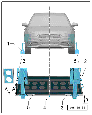
Overview Calibration Tool -VAS6350- with Peripheral Camera Calibration Device -VAS6350/6-
The Left Post With Plate -VAS6350/6-1- and Right Post With Plate -VAS6350/6-2- must be vertical.
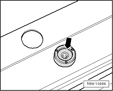
- Move the calibration field on the Calibration Tool -VAS6350-into a horizontal position.
- To do so, twist plastic feet under the calibration field of the Calibration Tool -VAS6350- so that air bubble in level is located exactly in the center of the indicator -arrow-
 WARNING
Make sure light does not reflect off the Peripheral Camera Calibration Device -VAS6350/6-.
Reflections affect the camera and may make it impossible to perform the calibration.
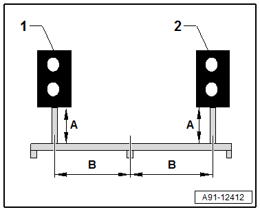
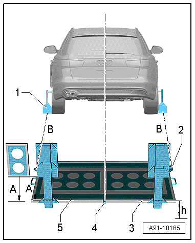
- Set the Left Post With Plate -VAS6350/6-1--1- and the Right Post With Plate -VAS6350/6-2--2- on both sides to the dimension -B- 77.5 of the scale on the Calibration Device -VAS6350-.
- Adjust the height of the Left Post With Plate -VAS6350/6-1--1- and Right Post With Plate -VAS6350/6-2--2- so that dimension -A- is 150 mm between the lower edge of the black measuring field (not of the aluminum frame!) and the surface of the Calibration Device -VAS6350- calibration field.
The corners on the outside of the Calibration Tool -VAS6350- calibration field must always be flush with the outer edge of the black line on the measuring field when performing distance measuring.
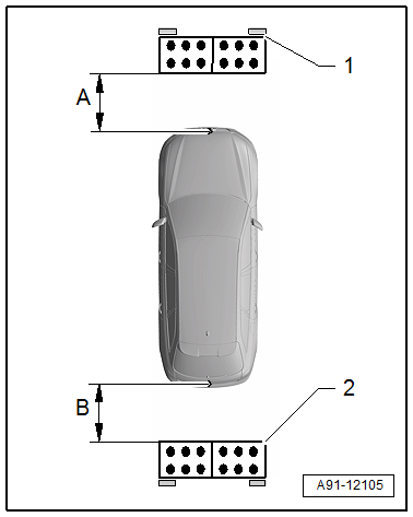
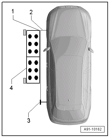
Layout of Calibration Tool -VAS6350- with Peripheral Camera Calibration Device -VAS6350/6-
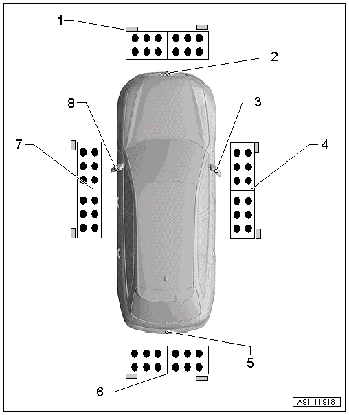
1 - Positioning the Front Peripheral Camera -R243- for calibrating
2 - Front Peripheral Camera -R243-
- Calibrating. Refer to → Chapter "Rear Peripheral Camera -R246-, Calibrating".
3 - Right Peripheral Camera -R245-
- Calibrating. Refer to → Chapter "Left Peripheral Camera -R244-/Right Peripheral Camera -R245-, Calibrating".
4 - Positioning the Right Peripheral Camera -R245- for calibrating
5 - Rear Peripheral Camera -R246-
- Calibrating. Refer to → Chapter "Rear Peripheral Camera -R246-, Calibrating".
6 - Positioning the Rear Peripheral Camera -R246- for calibrating
7 - Positioning the Left Peripheral Camera -R244- for calibrating
8 - Left Peripheral Camera -R244-
- Calibrating. Refer to → Chapter "Left Peripheral Camera -R244-/Right Peripheral Camera -R245-, Calibrating".
WARNING
Make sure light does not reflect off the Peripheral Camera Calibration Device -VAS6350/6-.
Reflections affect the camera and may make it impossible to perform the calibration.
Front Peripheral Camera -R243- Calibrating
Special tools and workshop equipment required
- Calibration Tool -VAS6350-
- Peripheral Camera Calibration Device -VAS6350/6-
- Vehicle Diagnostic Tester
The Front Peripheral Camera -R243- is installed in the bumper cover between the Audi rings (between Night Vision System Camera -R212- and Garage Door Opener Control Module -J530-).
- Setup requirements.
- Install and align the Calibration Tool -VAS6350- with Peripheral Camera Calibration Device - VAS6350/6-. Refer to → Chapter "Calibration Tool -VAS6350- with Peripheral Camera Calibration Device -VAS6350/6-, Installing and Aligning".
- Connect the Vehicle Diagnostic Tester.
Setting up the calibration device
Calibration Tool - Wheel Center Mountings -VAS6350/1- installing:
- Check the dimension of the holes.
- Equip the Calibration Tool - Wheel Center Mountings -VAS6350/1- appropriately.
- To do so, secure three wheel bolt adapters in the hole circle to each Calibration Tool - Wheel Center Mountings -VAS6350/1-.
- Place the paddle on both Calibration Tool - Wheel Center Mountings -VAS6350/1- and secure them using a clamping screw.
- Place the Calibration Tool - Wheel Center Mountings -VAS6350/1- onto the wheel bolts on the rear wheels.
The Calibration Tool - Wheel Center Mountings -VAS6350/1- are positioned by the "O rings" in the adapters and held in place.
 Note
Note
Attach the Calibration Tool - Wheel Center Mountings -VAS6350/1- onto the wheels so that any installed "anti-theft" wheel mounting bolts are not connected to the Calibration Tool - Wheel Center Mountings -VAS6350/1-.
- Adjust the paddle with aid of lock bolts so that they move freely just above the floor. Make sure that the paddle is easily accessible.
Calibration Tool -VAS6350- with Peripheral Camera Calibration Device -VAS6350/6- orientation
- Position the Calibration Tool -VAS6350- with the Night Vision Calibration Tool -VAS6350/6--1- at a distance of between 400 mm and 600 mm -dimension A- in front of the vehicle in the center (in front of the front bumper trim).
- Bring the Calibration Tool -VAS6350- with Night Vision Calibration Tool -VAS6350/6- into a horizontal position.
- To do so, twist plastic feet under the calibration field of the Calibration Tool -VAS6350- so that air bubble in level is located exactly in the center of the indicator -arrow-
WARNING
Make sure light does not reflect off the Peripheral Camera Calibration Device -VAS6350/6-.
Reflections affect the camera and may make it impossible to perform the calibration.
- Attach the Calibration Tool - Linear Laser -VAS6350/3--4- to the Night Vision Calibration Tool -VAS6350/6- to the center of the location provided.
- Switch on the Calibration Tool - Linear Laser -VAS6350/3--4- and align the calibration field of the Calibration Tool -VAS6350- with Peripheral Camera Calibration Device -VAS6350/6- so that the laser beam points at the front of the vehicle, in the center just above the Audi rings.
- Make sure the Audi rings are exactly in the center. Correct the laser beam accordingly.
Distance measurement:
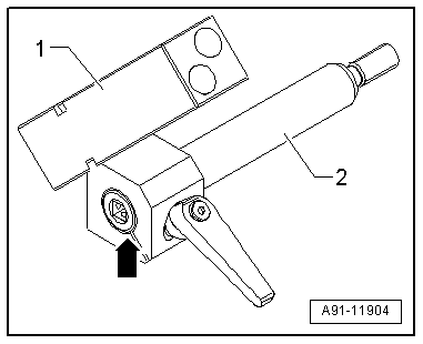
- Switch on the Calibration Tool - Spacing Laser -VAS6350/2-.
The following display appears:
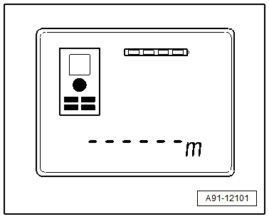
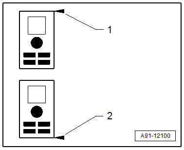
The display shows how to stop the Calibration Tool - Spacing Laser -VAS6350/2-. Press the corresponding button.
1 - Attach with front edge
2 - Attach with rear edge
- Hold the Calibration Tool - Spacing Laser -VAS6350/2--2- flush in the bracket on one side of the Calibration Tool -VAS6350- calibration field (with rear edge). To do so, the Calibration Tool - Spacing Laser -VAS6350/2--2- must sit securely on the bracket.
- Press the measuring button briefly.
The laser turns on.
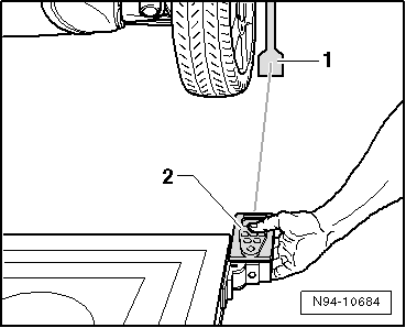
- Make sure that laser beam from Calibration Tool - Spacing Laser -VAS6350/2--2- hits lower, enlarged part of paddle -1-.
If this is not the case, paddles must be corrected accordingly via clamping screws on the Calibration Tool - Wheel Center Mountings -VAS6350/1-.
- Use one hand to secure the Calibration Tool - Spacing Laser -VAS6350/2- in the bracket on the calibration field Calibration Tool -VAS6350- while the laser beam is visible on the paddle.
- Then press the measuring button for distance measurement briefly.
- Repeat this measurement on the other side of the Calibration Tool -VAS6350- calibration field in the same way for the rear wheel.
The distance value must be the same on both sides.
If values are not identical:
- Align the Calibration Tool -VAS6350- with the Peripheral Camera Calibration Device -VAS6350/6- long enough so that both sides are identical.
Pay attention when aligning the Calibration Tool -VAS6350- with Peripheral Camera Calibration Device -VAS6350/6- that the Calibration Tool - Linear Laser -VAS6350/3- from the Peripheral Camera Calibration Device -VAS6350/6- strikes the center of the Audi rings and the indicator of the level remains centered. Adjust if necessary.
- Make note of the distance dimension measured.
Dimension measurement -h-:
- Measure the height of the Calibration Tool -VAS6350--2- calibration field, dimension -h-, from the surface of the Calibration Tool -VAS6350--2- calibration field (not the aluminum frame) down to the floor. Measure the hole in the Calibration Tool -VAS6350--2- calibration field.
Make sure the Calibration Tool - Spacing Laser -VAS6350/2--1- is adjusted correctly (attach with front edge).
The display shows how to stop the Calibration Tool - Spacing Laser -VAS6350/2-. Press the corresponding button.
1 - Attach with front edge
2 - Attach with rear edge
Dimension -h- and the distance dimension must now be entered into the Vehicle Diagnostic Tester in "millimetres".
Performing calibration
Vehicle Diagnostic Tester is attached.
- Select the Diagnostic mode and start the diagnostics.
- Select the tab test plan.
- Select select individual tests and choose the following sequence.
- Body
- Electrical Equipment
- 01 - OBD-capable systems
- 6C - peripheral camera control module | J928
- 6C - peripheral camera control module, functions
- 6C - Calibration, (Repair Group 91)
From here the Vehicle Diagnostic Tester advances the calibration procedure forward.
WARNING
Make sure light does not reflect off the Peripheral Camera Calibration Device -VAS6350/6-.
Reflections affect the camera and may make it impossible to perform the calibration.
Left Peripheral Camera -R244-/Right Peripheral Camera -R245-, Calibrating
Special tools and workshop equipment required
- Calibration Tool -VAS6350-
- Peripheral Camera Calibration Device -VAS6350/6-
- Vehicle Diagnostic Tester
The Left Peripheral Camera -R244-/Right Peripheral Camera -R245- are installed inside the left and right exterior mirrors.
The following describes calibrating the Left Peripheral Camera -R244-. Calibrating the Right Peripheral Camera -R245- is identical.
- Setup requirements.
- Install and align the Calibration Tool -VAS6350- with Peripheral Camera Calibration Device - VAS6350/6-. Refer to → Chapter "Calibration Tool -VAS6350- with Peripheral Camera Calibration Device -VAS6350/6-, Installing and Aligning".
- Connect the Vehicle Diagnostic Tester.
Setting up the calibration device
Calibration Tool - Wheel Center Mountings -VAS6350/1- installing:
- Check the dimension of the holes.
- Equip the Calibration Tool - Wheel Center Mountings -VAS6350/1- appropriately. Use spacer pieces.
- To do so, secure three wheel bolt adapters in the hole circle to each Calibration Tool - Wheel Center Mountings -VAS6350/1-.
- Place the paddle on both Calibration Tool - Wheel Center Mountings -VAS6350/1- and secure them using a clamping screw.
- Place the Wheel Center Mounting -VAS6350/1- onto the wheel bolts on the front wheels.
The Calibration Tool - Wheel Center Mountings -VAS6350/1- are positioned by the "O rings" in the adapters and held in place.
Note
Attach the Calibration Tool - Wheel Center Mountings -VAS6350/1- onto the wheels so that any installed "anti-theft" wheel mounting bolts are not connected to the Calibration Tool - Wheel Center Mountings -VAS6350/1-.
- Position the equipped Calibration Tool -VAS6350- with the Peripheral Camera Calibration Device -VAS6350/6--4- near the vehicle.
- Adjust the paddle -2- with a clamping screw so that it moves freely and easily just over the Calibration Tool -VAS6350--4- calibration platform.
Installing the Calibration Tool - Linear Laser -VAS6350/3-:
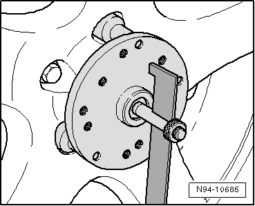
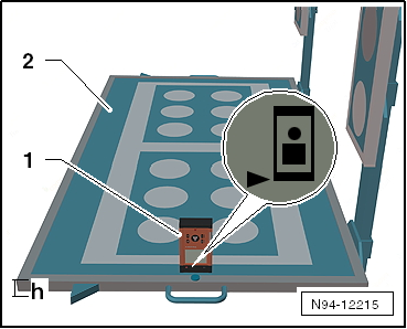
- Install the Guide Pin -VAS6350/6-5--2- all the way using the 3/8" fine toothed ratchet on the left rear wheel and install the Line Scan Laser Mount -VAS6350/6-6- together with the Left Post Mount -VAS6350/3--1-.
- Slide the Line Scan Laser Mount -VAS6350/6-6- so that the outer edge of the Guide Pin -VAS6350/6-5- is flush with the outer edge of the laser housing -arrow-. Tighten the clamping lever.
Calibration Tool -VAS6350- with Peripheral Camera Calibration Device -VAS6350/6- orientation
- Switch on the Calibration Tool - Linear Laser -VAS6350/3--3- and adjust the laser beam forward toward the Calibration Tool - Wheel Center Mountings -VAS6350/1--2- such that a line appears on the Calibration Tool -VAS6350--4- calibration field.
- Adjust the Calibration Tool -VAS6350--4- calibration field such that the outer edge of the black line on the Calibration Tool -VAS6350--4- calibration field is exactly on the laser beam.
- Adjust the Calibration Tool -VAS6350--4- calibration field relative to the outer edge of the black line -1- so that it lines up exactly with the free-hanging paddle on the Calibration Tool - Wheel Center Mountings -VAS6350/1--2-.
- Bring the Calibration Tool -VAS6350- with Night Vision Calibration Tool -VAS6350/6- into a horizontal position.
- To do so, twist plastic feet under the calibration field of the Calibration Tool -VAS6350- so that air bubble in level is located exactly in the center of the indicator -arrow-
WARNING
Make sure light does not reflect off the Peripheral Camera Calibration Device -VAS6350/6-.
Reflections affect the camera and may make it impossible to perform the calibration.
- Measure the height of the Calibration Tool -VAS6350--2- calibration field, dimension -h-, from the surface of the Calibration Tool -VAS6350--2- calibration field (not the aluminum frame) down to the floor. Measure the hole in the Calibration Tool -VAS6350--2- calibration field.
Make sure the Calibration Tool - Spacing Laser -VAS6350/2--1- is adjusted correctly (attach with front edge).
The display shows how to stop the Calibration Tool - Spacing Laser -VAS6350/2-. Press the corresponding button.
1 - Attach with front edge
2 - Attach with rear edge
Dimension -h- and the distance dimension must now be entered into the Vehicle Diagnostic Tester in "millimetres".
Performing calibration
Vehicle Diagnostic Tester is attached.
- Select the Diagnostic mode and start the diagnostics.
- Select the tab test plan.
- Select select individual tests and choose the following sequence.
- Body
- Electrical Equipment
- 01 - OBD-capable systems
- 6C - peripheral camera control module | J928
- 6C - peripheral camera control module, functions
- 6C - Calibration, (Repair Group 91)
From here the Vehicle Diagnostic Tester advances the calibration procedure forward.
WARNING
Make sure light does not reflect off the Peripheral Camera Calibration Device -VAS6350/6-.
Reflections affect the camera and may make it impossible to perform the calibration.
Rear Peripheral Camera -R246-, Calibrating
Special tools and workshop equipment required
- Calibration Tool -VAS6350-
- Peripheral Camera Calibration Device -VAS6350/6-
- Vehicle Diagnostic Tester
The Rear Peripheral Camera -R246- is installed in the rear lid handle button.
- Setup requirements.
- Install and align the Calibration Tool -VAS6350- with Peripheral Camera Calibration Device - VAS6350/6-. Refer to → Chapter "Calibration Tool -VAS6350- with Peripheral Camera Calibration Device -VAS6350/6-, Installing and Aligning".
- Connect the Vehicle Diagnostic Tester.
Setting up the calibration device
Calibration Tool - Wheel Center Mountings -VAS6350/1- installing:
- Check the dimension of the holes.
- Equip the Calibration Tool - Wheel Center Mountings -VAS6350/1- appropriately. Use spacer pieces.
- To do so, secure three wheel bolt adapters in the hole circle to each Calibration Tool - Wheel Center Mountings -VAS6350/1-.
- Place the paddle on both Calibration Tool - Wheel Center Mountings -VAS6350/1- and secure them using a clamping screw.
- Place the Calibration Tool - Wheel Center Mountings -VAS6350/1- onto the wheel bolts on the rear wheels.
The Calibration Tool - Wheel Center Mountings -VAS6350/1- are positioned by the "O rings" in the adapters and held in place.
Note
Attach the Calibration Tool - Wheel Center Mountings -VAS6350/1- onto the wheels so that any installed "anti-theft" wheel mounting bolts are not connected to the Calibration Tool - Wheel Center Mountings -VAS6350/1-.
- Adjust the paddle with aid of lock bolts so that they move freely just above the floor. Make sure that the paddle is easily accessible.
Calibration Tool -VAS6350- with Peripheral Camera Calibration Device -VAS6350/6- orientation
- Position the Calibration Tool -VAS6350- with the Night Vision Calibration Tool -VAS6350/6--1- at a distance of between 400 mm and 600 mm -dimension B- in the rear of the vehicle in the center (in behind of the rear bumper trim).
Calibration Tool -VAS6350- with Peripheral Camera Calibration Device -VAS6350/6- orientation
- Move the calibration field on the Calibration Tool -VAS6350-into a horizontal position.
- To do so, twist plastic feet under the calibration field of the Calibration Tool -VAS6350- so that air bubble in level is located exactly in the center of the indicator -arrow-
WARNING
Make sure light does not reflect off the Peripheral Camera Calibration Device -VAS6350/6-.
Reflections affect the camera and may make it impossible to perform the calibration.
- Attach the Calibration Tool - Linear Laser -VAS6350/3--4- to the Calibration Tool -VAS6350- to the center of the location provided.
- Switch on the Calibration Tool - Linear Laser -VAS6350/3--4- on the calibration field of the Calibration Tool -VAS6350- and align the entire Calibration Tool -VAS6350- with Peripheral Camera Calibration Device -VAS6350/6- so that the laser beam of the Calibration Tool - Linear Laser -VAS6350/3- hits the center of vehicle rear above the Audi rings.
- Make sure the Audi rings are centered on the rear. Correct the laser beam accordingly.
Distance measurement:
- Switch on the Calibration Tool - Spacing Laser -VAS6350/2-.
The following display appears:
The display shows how to stop the Calibration Tool - Spacing Laser -VAS6350/2-. Press the corresponding button.
1 - Attach with front edge
2 - Attach with rear edge
- Hold the Calibration Tool - Spacing Laser -VAS6350/2--2- flush in the bracket on one side of the Calibration Tool -VAS6350- (attach with rear edge). The Calibration Tool - Spacing Laser -VAS6350/2--2- must sit securely on the bracket.
- Press the measuring button briefly.
The laser turns on.
- Make sure that laser beam from Calibration Tool - Spacing Laser -VAS6350/2--2- hits lower, enlarged part of paddle -1-.
If this is not the case, paddles must be corrected accordingly via clamping screws on the Calibration Tool - Wheel Center Mountings -VAS6350/1-.
- Use one hand to secure the Calibration Tool - Spacing Laser -VAS6350/2- in the bracket on the Calibration Tool -VAS6350- while the laser beam is visible on the paddle.
- Then press the measuring button for distance measurement briefly.
- Repeat this measurement on the other side of the Calibration Tool -VAS6350- in the same way for the rear wheel.
The distance value must be the same on both sides.
If values are not identical:
- Align the Calibration Tool -VAS6350- long enough so that both sides are identical.
Pay attention when aligning the calibration field of the Calibration Tool -VAS6350-, that the Calibration Tool - Linear Laser -VAS6350/3- from the Calibration Tool -VAS6350- strikes the center of the Audi rings and the indicator of the level remains centered. Adjust if necessary.
- Make note of the distance dimension measured.
Dimension measurement -h-:
- Measure the height of the Calibration Tool -VAS6350--2- calibration field, dimension -h-, from the surface of the Calibration Tool -VAS6350--2- calibration field (not the aluminum frame) down to the floor. Measure the hole in the Calibration Tool -VAS6350--2- calibration field.
Make sure the Calibration Tool - Spacing Laser -VAS6350/2--1- is adjusted correctly (attach with front edge).
The display shows how to stop the Calibration Tool - Spacing Laser -VAS6350/2-. Press the corresponding button.
1 - Attach with front edge
2 - Attach with rear edge
Dimension -h- and the distance dimension must now be entered into the Vehicle Diagnostic Tester in "millimeters".
Performing calibration
Vehicle Diagnostic Tester is attached.
- Select the Diagnostic mode and start the diagnostics.
- Select the tab test plan.
- Select select individual tests and choose the following sequence.
- Body
- Electrical Equipment
- 01 - OBD-capable systems
- 6C - peripheral camera control module | J928
- 6C - peripheral camera control module, functions
- 6C - Calibration, (Repair Group 91)
From here the Vehicle Diagnostic Tester advances the calibration procedure forward.
WARNING
Make sure light does not reflect off the Peripheral Camera Calibration Device -VAS6350/6-.
Reflections affect the camera and may make it impossible to perform the calibration.
Special Tools
Special tools and workshop equipment required
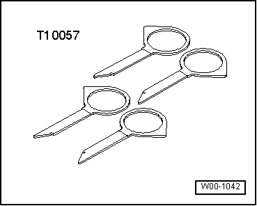
- Radio Removal Tool -T10057-
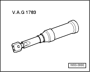
- Torque Wrench 1783 - 2-10Nm -VAG1783-
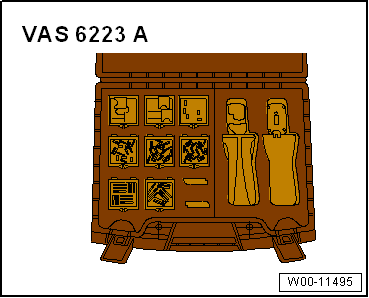
- Fiber-Optic Repair Set -VAS6223B-
- Fiber-Optic Repair Set - Connector Protective Caps -VAS 6223/9-.
- Calibration Tool -VAS6350-
- Peripheral Camera Calibration Device -VAS6350/6-
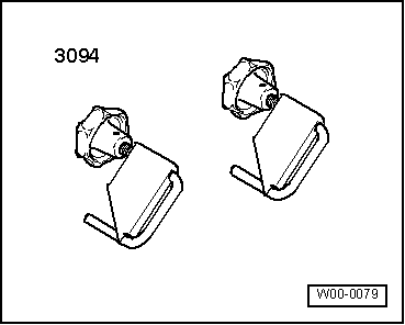
- Hose Clamps - Up To 25mm -3094-
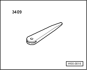
- Trim Removal Wedge -3409-
Revision History
DRUCK NUMBER: A005A000421
.png)
.png)
