Audi A6 Typ 4G: Instrument Panel Central Tube, Removing and Installing
Removing
- Remove the instrument panel. Refer to → Chapter "Instrument Panel, Removing and Installing".
- Country-specific with knee airbag: remove the driver side knee airbag. Refer to → Chapter "Driver Side Knee Airbag with Igniter, Removing and Installing".
- Unbolt steering column from the instrument panel central tube and lay it on the floor of the vehicle. Refer to → Suspension, Wheels, Steering; Rep. Gr.48; Steering Column; Steering Column, Removing and Installing.
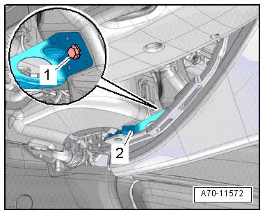
- Remove the screw -3- from the expanding clip and disengage the left instrument panel vent air duct -1- - driver side on the central tube -2-.
- Remove the front passenger side right instrument panel vent air guide on the instrument panel central tube. Refer to → Heating, Ventilation and Air Conditioning; Rep. Gr.87; Air Guide; Air Distribution Channels, Removing and Installing.
- Remove the defroster vent air guide and the "indirect ventilation" vent for the windshield. Refer to → Heating, Ventilation and Air Conditioning; Rep. Gr.87; Air Guide; Air Guide for the Defrost Air Vent, Removing and Installing.
- Remove the center instrument panel vent air guide. Refer to → Heating, Ventilation and Air Conditioning; Rep. Gr.87; Air Guide; Center Instrument Panel Vent Air Guide, Removing and Installing.
- Remove the Air Conditioning (A/C) unit bracket. Refer to → Chapter "A/C Unit Bracket, Removing and Installing".
- Remove the Fuse Panel B -SB- on the left side and the Fuse Panel C -SC- on the right side from the instrument panel central tube. Refer to → Electrical Equipment; Rep. Gr.97; Relay Carriers, Fuse Panels and E-Boxes; Overview - Relay Carriers, Fuse Panels and E-Boxes.
- Disconnect the connectors, unclip wires on the instrument panel central tube and free them up.
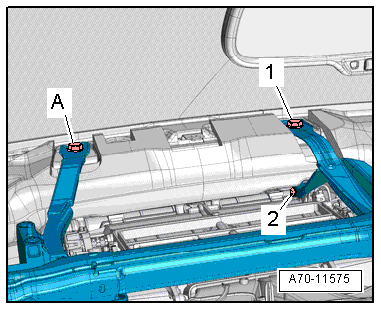
- Remove the screw -1- on the top brace on the instrument panel central tube.
- Remove the A/C unit bolt -2- on the instrument panel central tube top brace.
- Vehicles with windshield projection head up display: remove the screw -A- from the bracket for the windshield projection head up display control module.
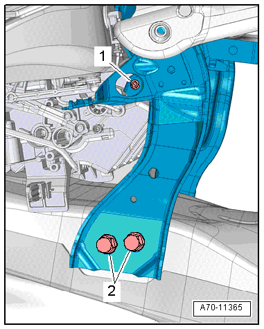
- Remove bolt -1- for A/C unit on the left and right central tube supports.
 Caution
Mark height and side position on instrument panel central tube for reinstallation.
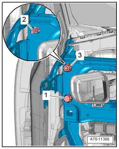
- Remove left and right bolts -2- for instrument panel central tube supports.
- Remove left and right bolt -1- from the instrument panel central tube.
- Remove the left and right nut -3- from the instrument panel central tube.
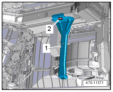
- Remove the threaded pin -2- from the instrument panel central tube.
 Note
Note
Two technicians are needed to remove instrument panel central tube.
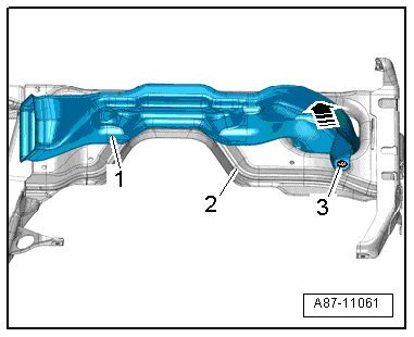
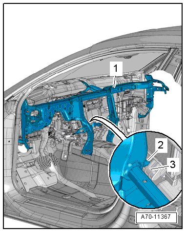
- Carefully pull out the instrument panel central tube -1- on the driver side and at the same time, disengage it from the air conditioner -3- and bracket -2-.
- Remove the instrument panel central tube from the threaded pin on the A-pillar on the front passenger side.
- Carefully tilt the top side of the instrument panel central tube back while pulling it up.
- Remove the instrument panel central tube from the vehicle interior.
Installing
- Carefully insert the instrument panel central tube -1- in the body.
- Attach the instrument panel central tube to the air conditioner -3- and to the bracket -2-.
- Install the threaded pin into the mount on the A-pillar on the driver side and tighten it.
- Align instrument panel central tube according to the marks applied to the A-pillar during removal.
- Tighten the nuts and bolts for the instrument panel central tube near the A-pillar on both the driver and front passenger sides.
Installation is performed in reverse order of removal, while noting the following:
- Install the steering column. Refer to → Suspension, Wheels, Steering; Rep. Gr.48; Steering Column; Overview - Steering Column.
Check the installation location of the instrument panel central tube
- Insert instrument panel to test.
- Secure instrument panel at left and right to instrument panel central tube.
- Close doors.
- Check whether gap dimension between instrument panel and left and right doors is even.
- Check whether height of instrument panel aligns with molding in door trim.
- If the adjustment is incorrect, note lateral and/or vertical deviation.
- Loosen instrument panel central tube screws.
- Insert instrument panel central tube according to the noted deviations.
- Tighten the bolt -1- and nut -3- for the instrument panel central tube near the A-pillar on both the driver and front passenger sides.
 WARNING
Ignition must be on when connecting battery. If pyrotechnic components (for example, airbag, belt tensioner) are not repaired correctly, they may deploy unintentionally after connecting battery. There must not be anyone inside the vehicle when connecting the battery.
DANGER!
When working on vehicles with the ignition already switched on or that are ready to drive there is a danger of the engine starting unexpectedly and of being poisoned by gas in enclosed areas. Risk of body parts and/or clothing being clamped or pulled.
Perform the following before switching on the ignition:
- Move the selector lever into P.
- Activate the parking brake
- Turn off the ignition.
- Open the hood
- Connect the charger, such as the Battery Charger -VAS5095A- to the jump start of the 12V vehicle electrical system.
- Turn on the ignition.
- Connect the battery Ground (GND) cable with the ignition turned on. Refer to → Electrical Equipment; Rep. Gr.27; Battery; Battery, Disconnecting and Connecting.
Note
If the Airbag Indicator Lamp -K75- indicates a fault, check the Diagnostic Trouble Code (DTC) memory, erase it and check it again. Refer to Vehicle Diagnostic Tester.
Installation notes, for example tightening specifications, replacing components. Refer to → Chapter "Overview - Instrument Panel Central Tube".
Mounting Bracket, Removing and Installing
Removing
- Remove the instrument panel central tube → Chapter "Instrument Panel Central Tube, Removing and Installing".
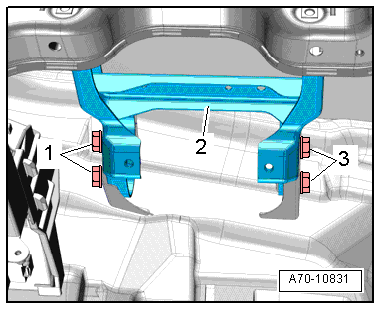
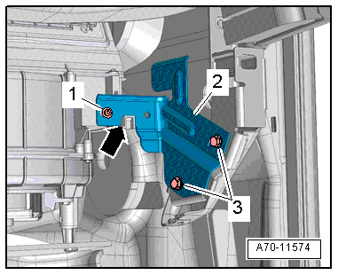
- Remove the bolts -1 and 3- and then remove the bracket -2-.
Installing
- Insert mounting bracket in the mount on the windshield frame and affix only loosely with bolts -1 and 3-.
Installation is performed in reverse order of removal, while noting the following:
Note
The mounting bracket can be correctly positioned only when the central tube is installed.
- First tighten the steering column with the mounting bracket to the central tube. Refer to → Suspension, Wheels, Steering; Rep. Gr.48; Steering Column; Overview - Steering Column.
- Then tighten bolts -1 and 3- for mounting bracket.
Installation notes, for example tightening specifications, replacing components. Refer to → Chapter "Overview - Instrument Panel Central Tube".
Glove Compartment Bracket, Removing and Installing
Glove Compartment Bracket, Removing and Installing
Removing
- Remove the glove compartment. Refer to → Chapter "Glove Compartment, Removing and Installing".
- Remove the bolts -1-.
- Remove glove compartment bracket -2-.
Installing
Install in reverse order of removal. Note the following:
Installation notes, for example tightening specifications, replacing components. Refer to → Chapter "Overview - Instrument Panel Central Tube".
Glove Compartment Bracket, Removing and Installing, Knee Airbag
Removing
- Remove the glove compartment. Refer to → Chapter "Glove Compartment, Removing and Installing, with Knee Airbag".
- Remove the front passenger side right instrument panel vent air guide on the instrument panel central tube. Refer to → Heating, Ventilation and Air Conditioning; Rep. Gr.87; Air Guide; Air Distribution Channels, Removing and Installing.
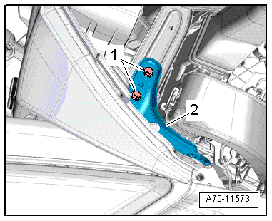
- Remove the bolt -2- from the bracket on the instrument panel central tube.
- Remove the bracket -1-.
Installing
Install in reverse order of removal. Note the following:
Installation notes, for example tightening specifications, replacing components. Refer to → Chapter "Overview - Instrument Panel Central Tube".
Instrument Panel Central Tube Bracket/Support, Removing and Installing
A/C Unit Bracket, Removing and Installing
Removing
- Remove the glove compartment. Refer to → Chapter "Glove Compartment, Removing and Installing".
- Remove the bolts -1 and 3-.
- Disengage the bracket -2- at the A/C unit -arrow- and remove it.
Installing
- Insert bracket on the A/C unit -arrow- and fasten with bolt -1-.
Installation is performed in reverse order of removal, noting the following:
Installation notes, for example tightening specifications, replacing components. Refer to → Chapter "Overview - Instrument Panel Central Tube".
Instrument Panel Cover Bracket, Removing and Installing
Removing
- Remove the instrument panel cover on the driver side. Refer to → Chapter "Driver Side Instrument Panel Cover, Removing and Installing".
- Remove the bolt -1-.
- Remove the instrument panel cover bracket -2-.
Installing
Install in reverse order of removal. Note the following:
Installation notes, for example tightening specifications, replacing components. Refer to → Chapter "Overview - Instrument Panel Central Tube".
Knee Airbag Bracket, Removing and Installing
Removing
- Remove the glove compartment. Refer to → Chapter "Glove Compartment, Removing and Installing, with Knee Airbag".
- Remove the front passenger side right instrument panel vent air guide on the instrument panel central tube. Refer to → Heating, Ventilation and Air Conditioning; Rep. Gr.87; Air Guide; Air Distribution Channels, Removing and Installing.
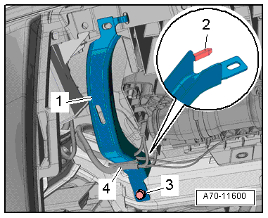
- Unclip the wire holder -4- from the bracket.
- Remove the bolt -3- for the bracket on the instrument panel central tube.
- Remove the bracket -1- and rubber grommet -2-.
Installing
Install in reverse order of removal. Note the following:
- Position the bracket -1- with the rubber grommet -2- so that the tab engages in the hole inside the instrument panel.
Installation notes, for example tightening specifications, replacing components. Refer to → Chapter "Overview - Instrument Panel Central Tube".