Audi A6 Typ 4G: Refrigerant Cut-Off Valve
 Note
Note
- There are different versions of the shut-off valve with different functions and with different names. The following illustrated Hybrid Battery Refrigerant Shut-Off Valve 1 -N516- is for example installed on an Audi Q7 hybrid. Refer to → Heating, Ventilation and Air Conditioning; Rep. Gr.87; Refrigerant Circuit; System Overview - Refrigerant Circuit.
- There are various designations, depending on the function and the vehicle. Refer to → Heating, Ventilation and Air Conditioning; Rep. Gr.87; Refrigerant Circuit; System Overview - Refrigerant Circuit.
Shut-Off Valve with Two Switching States (Open Or Closed)
- Hybrid Battery Refrigerant Shut-Off Valve 1 -N516- (for example the Audi Q5 Hybrid)
- Heater and A/C Unit Refrigerant Shut-Off Valve -N541- (for example on Audi A3 e-tron)
- High-Voltage Battery Heater Core Refrigerant Shut-Off Valve -N542- (for example on Audi A3 e-tron)
- Refrigerant Shut-Off Valve -V424- (for example on Audi Q7 e-tron)
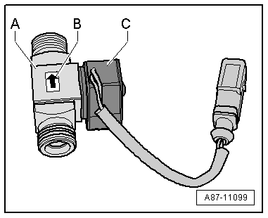
- If the shut-off -A- is not activated by the electronics, it is open and lets the refrigerant flow through to the evaporator in the A/C unit.
- The shut-off valve -A- is installed on vehicles with the battery cooling module. It is activated in hybrid mode when no A/C system operation is desired for the passenger compartment or for the Hybrid Battery Unit -AX1-, but is necessary for battery cooling.
- Observe the arrow -B- attached to the shut-off valve -A-, which shows the flow direction of the refrigerant (from the condenser to the evaporator in the A/C unit)
- The solenoid coil -C- attached to the shut-off valve is activated for example from the Battery Regulation Control Module -J840- → Wiring diagrams, Troubleshooting & Component locations. Use the Vehicle Diagnostic Tester in the "Guided Fault Finding" Function for the A/C System and the Battery Regulation.
- On a vehicle with two evaporators (one in the A/C unit and one for example on the Audi Q5 Hybrid) in the battery cooling module, if the measured temperature on one of the evaporators corresponds to the target value or the target value falls short, but does not reach the required target value on the other evaporator, the following adjustment is performed: the relevant control module (for example the Battery Regulation Control Module -J840- n the Audi Q5 hybrid) activates the electric A/C compressor with increased speed (thereby increasing the A/C cooling output and decreasing the pressure on the low pressure side as well as the evaporator temperature) via the A/C Compressor Control Module -J842-. If the target value falls short for the temperature of one of the evaporators, the relevant control module (for example the Battery Regulation Control Module -J840- on the Audi Q5 Hybrid the Hybrid Battery Refrigerant Shut-Off Valve 1 -N516- or the Hybrid Battery Refrigerant Shut-Off Valve 2 -N517-) activates so that the evaporator which is too cold is no longer supplied with refrigerant. Use the Vehicle Diagnostic Tester in the "Guided Fault Finding" Function for the A/C System and → Heating, Ventilation and Air Conditioning; Rep. Gr.87; System Overview - Refrigerant Circuit (for the specific vehicle).
Shut-Off Valve, which is Regulated via the Characteristic Curve
- Refrigerant Shut-Off Valve 2 -N640- through Refrigerant Shut-Off Valve 5 -N643- (for example on Audi Q7 e-tron)
- Refrigerant Expansion Valve 1 -N636- (for example on Audi Q7 e-tron)
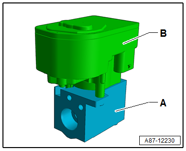
- The shut-off valve -A- is activated via a step motor -B- from the respective control module via the characteristic curve (opened or closed).
- If the shut-off valve works as a regulator valve (for example on the Audi Q7 as Refrigerant Expansion Valve 1 -N636-) it is only open until the temperature for the heat exchanger is reached. Refer to → Heating, Ventilation and Air Conditioning; Rep. Gr.87; Refrigerant Circuit; System Overview - Refrigerant Circuit.
- Shut-off valves activated via the step motor do not have a specified resting position. For this reason before performing procedures on the refrigerant circuit it must be set to a specified position (open or closed). Refer to → Heating, Ventilation and Air Conditioning; Rep. Gr.87; Refrigerant Circuit; System Overview - Refrigerant Circuit.
- Depending on the design of the refrigerant circuit multiple shut-off valves can be combined in one valve block (for example on the Audi Q7 e-tron). Refer to → Heating, Ventilation and Air Conditioning; Rep. Gr.87; Refrigerant Circuit; System Overview - Refrigerant Circuit.
- The step motor is adapted and activated via the data wires (LIN Bus) from the respective control module according to its component location. Refer to → Heating, Ventilation and Air Conditioning; Rep. Gr.87; Refrigerant Circuit; System Overview - Refrigerant Circuit. Use the Vehicle Diagnostic Tester in the "Guided Fault Finding" function.
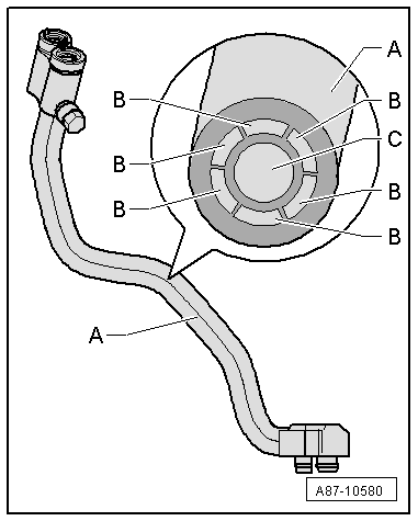
Refrigerant Line with Inner Heat Exchanger
In this refrigerant pipe, the flowing fluid warm refrigerant on the high pressure side is delivered into the low pressure side as flowing, vapor, cold refrigerant to increase the efficiency of the A/C system.
Note
This illustration shows a refrigerant pipe with an inner heat exchanger that is installed in the Audi A4 from MY 2008 and on the Audi A5 Coupe from MY 2008. Refer to → Heating, Ventilation and Air Conditioning; Rep. Gr.87; System Overview - Refrigerant Circuit (vehicle-specific repair manual).
A - Refrigerant line with inner heat exchanger
B - Channel inside the refrigerant pipe through with the warm fluid refrigerant flows to the evaporator (refrigerant circuit high pressure side)
C - Channel inside the refrigerant pipe in which the vapor of cold refrigerant flow to the A/C compressor (refrigerant circuit low pressure side)
Quick-Release Connections on Refrigerant Lines
 WARNING
The quick-release coupling connectors may be unlocked and opened only if the refrigerant circuit is empty.
Note
- This illustration shows the quick-coupling connection with a refrigerant pipe with an inner heat exchanger that is installed in the Audi A4 from MY 2008 and on the Audi A5 Coupe from MY 2008. Refer to → Heating, Ventilation and Air Conditioning; Rep. Gr.87; System Overview - Refrigerant Circuit (vehicle-specific repair manual).
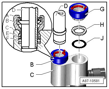
- The retaining ring -A- must be opened using, for example, the Air Conditioner Couplings Release Tool -T40149- in order to remove the refrigerant line -D-. Refer to → Heating, Ventilation and Air Conditioning; Rep. Gr.87; System Overview - Refrigerant Circuit (vehicle-specific repair manual).
- The quick-release coupling connectors -B- and -G- are to be replaced after removing the refrigerant line with the respective support ring -E- or -H- and O-ring -F- or -J-. Refer to → Heating, Ventilation and Air Conditioning; Rep. Gr.87; System Overview - Refrigerant Circuit (vehicle-specific repair manual) and the Parts Catalog).
A - Retaining ring (inside the quick-release coupling connector, high pressure side)
B - Quick-release coupling connector with retaining ring "high pressure side"
C - Refrigerant line with an inner heat exchanger
D - Refrigerant line "high pressure side"
E - Support ring "high pressure side"
F - O-ring "high pressure side"
G - Quick-release coupling connector with retaining ring "low pressure side"
H - Support ring "low pressure side"
J - O-ring "low pressure side"
Note
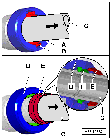
- There are different quick-release coupling versions -A- and -D-. The refrigerant lines -C-, for example, can unlocked and removed using the Air Conditioner Couplings Release Tool -T40149/1- in the same manner for both versions of the quick-release couplings.
- The check pins on the -B- quick-release couplings -A- installed at SOP are visible -C-, when the locked refrigerant line -C- is pulled in the direction of arrow.
- Beginning with MY 2010, as a running change, the quick-release coupling -D- and the refrigerant line -C- are being installed in the same manner as the quick-release coupling -A-. If the refrigerant line -C- is pulled in the direction of arrow after assembling, the ring -E- will come out of the quick-release coupling -D- installed and will show that the retaining ring -F- is completely latched to the refrigerant line -C-. Then the ring -E- can be removed from the refrigerant line -C-.
O-Ring Seals
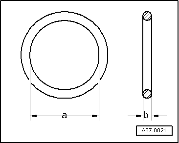
These rings seal off the connection points between individual components of the refrigerant circuit.
Only O-rings that are resistant to refrigerant R134a and refrigerant oil must be installed. Make sure they are original replacement parts.
O-ring seals:
- Always use only once.
- Make sure diameters -a- and -b- are correct.
- Coat with refrigerant oil before installing. Refer to → Heating, Ventilation and Air Conditioning; Rep. Gr.87; System Overview - Refrigerant Circuit (vehicle-specific repair manual) and the Parts Catalog.
Note
The color coding of refrigerant circuit O-rings with R134a has been discontinued. Black and colored O-rings are used. Refer to the Parts Catalog and → Heating, Ventilation and Air Conditioning; Rep. Gr.87; System Overview - Refrigerant Circuit (vehicle-specific repair manual).
Refrigerant Circuit Pipes and Hoses
The mixture of refrigerant oil and refrigerant R134a corrodes certain metals (such as copper) and alloys and dissolves some hose materials. Therefore use original replacement parts only.
Pipes and hoses are joined by threaded connections or special plug connectors.
Note
Observe specified torque for threaded connections, use appropriate release tools for plug connectors.
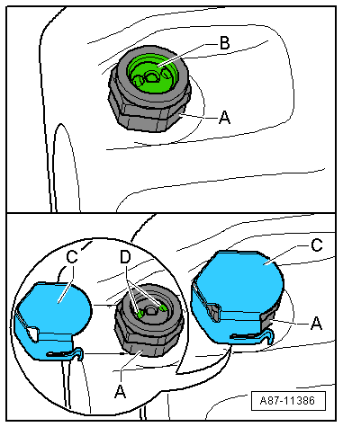
Pressure Relief Valve
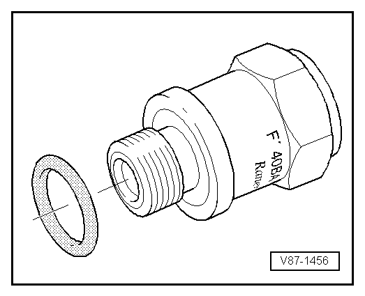
The pressure relief valve is installed on the A/C compressor or receiver/dryer.
At a pressure of approximately 38 bar (551 psi) positive pressure, valve opens and closes again once pressure has dissipated (approximately 30 bar (435 psi) ).
Refrigerant does not escape completely.
Note
- Depending on the version, a transparent plastic disc -B- may be installed on the pressure relief valve -A-, which breaks off as soon as the valve is activated.
- Depending on the pressure relief valve version -A-, an additional cover -C- can be slid onto the pressure relief valve -A-. If the pressure in the refrigerant circuit does rise above the pressure relief valve -A- opening pressure and the valve opens, the refrigerant does not escape in one direction, but rather it is distributed through the openings -D- under the cover -C-.
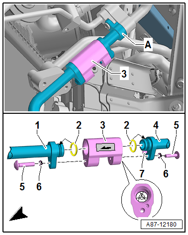
Check Valvesv
The check valves disconnect in different areas of the refrigerant circuit.
Note
- The illustrated check valve -3- if for example installed on an Audi Q7 e-tron
- The check valves in the refrigerant circuit in the flow direction have a specified residual pressure, approximately 0.1 bar or 100 mbar (1.5 psi). So that the refrigerant circuit can be completely evacuates (residual pressure less than 5 mbar (0.10 psi) ) all electrically activated valves must be opened.
- Depending on the version the flow direction can be marked using a sticker.