Audi A6 Typ 4G: Actuator, Removing and Installing
Rear Lid Motor 1 -V444-, Removing and Installing, Sedan
 WARNING
Adapt the Rear Lid Motor 1 -V444- whenever it is removed and installed. Use Guided Functions in Guided Fault Finding and diagnostic address 6D. Refer to Vehicle Diagnostic Tester.
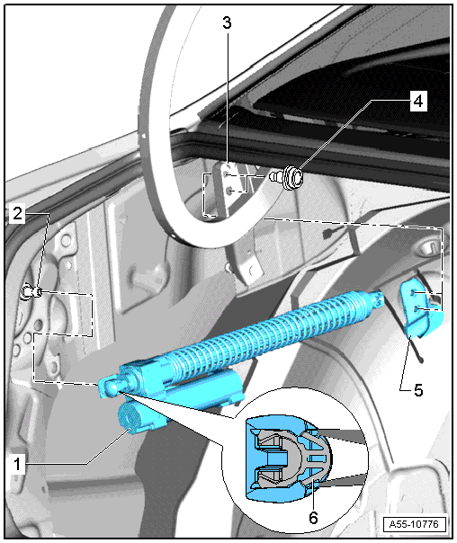
1 - Rear Lid Motor 1 -V444-
- Removing
- Disconnect the connector from the motor.
- Remove the Rear Lid Motor 1 -V444- from the rear ball stud.
- Remove the bolts from the bracket -5- and lift the Rear Lid Motor 1 -V444- out of the vehicle.
- Pull the Rear Lid Motor 1 -V444- off the ball studs on the bracket.
- Installing
- Push the Rear Lid Motor 1 -V444- onto the ball studs on the bracket and then tighten it.
2 - Ball Stud
- 20 Nm
3 - Rear Lid Hinge
4 - Bolt
- 21 Nm
5 - Bracket
6 - Plastic clip
- Must be removed using needle nose pliers. Refer to → Chapter "Gas-Filled Strut with Clip, Removing and Installing"
Rear Lid Motor 1 and 2 -V444-/-V445-, Removing and Installing, Avant
WARNING
Perform an adaptation using Guided Functions in Guided Fault Finding under diagnosis address 6D after removing and installing Rear Lid Motor 1 -V444- or Rear Lid Motor 2 -V445-. Refer to Vehicle Diagnostic Tester.
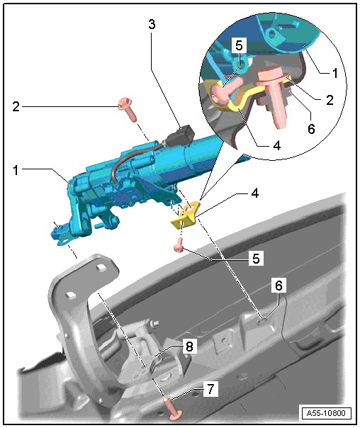
1 - Rear Lid Motor 2 -V445-
- The rear roof panel trim is removed. Refer to → Body Interior; Rep. Gr.70; Roof Trim Panels.
- Loosen the D-pillar trim in the drive area, and if necessary, carefully push it aside.
- On vehicles with power luggage compartment cover the D-pillar trim panel must be completely removed.
 Note
Note
- Remove or install drive unit only when rear lid is completely open.
- Before removing driving unit, loosen lock nuts on eccentric bolts.
- Remove the connector -2-.
- Loosen the lock nut on the drive unit.
Note
The eccentric bolt -item 1- must be loose in the hinge arm hole.
- Release tension on eccentric bolts with a brief turn to the right, if necessary.
- Remove the bolt -5- on the bracket -4-.
- Remove the screw in the hinge arm -item 7- and remove the drive unit -1- sideways.
2 - Bolt
- 21 Nm
3 - Connector
- Disconnect the connector before removing the drive unit.
4 - Bracket
Note
- Bracket is positioned with a device in factory and must not be adjusted.
- If bracket must be replaced, for example, when doing repairs after an accident, proceed as follows.
- Rear lid must be installed with the gas-filled strut.
- Secure the bracket -4- lightly with a screw -5- on the drive unit first.
- Bracket must still be moveable.
- Attach drive unit on rear lid hinge parallel to axle until it comes in contact with motor socket.
 Caution
Drive unit bushing must fit flat against hinge axle collar.
- Secure the bracket -4- on the body side with the bolt -3- and tighten to 21 Nm.
- Tighten the bolt -5- to 8 Nm.
- Tighten the eccentric bolt with the lock nut to the drive unit to the tightening specification.
Note
- Upon tightening locking nuts, eccentric bolts are braced in hinge with no play.
- For this reason, you cannot counterhold eccentric bolt hex head with an open-end wrench when tightening locking nuts.
- When removing drive unit, this tension is released with a small turn to the right on eccentric bolt hex head, after you have loosened locking nuts.
- Tighten the bolt to the drive fork. Refer to -item 7- to the tightening specification.
5 - Bolt
- 8 Nm
6 - Roof Frame
7 - Bolt
- Self-threading
- Tightening specification. Refer to -item 7-.
8 - Lid Hinge
- Removing and installing. Refer to → Chapter "Hinges, Removing and Installing, Avant".
Install the Rear Lid Motor 2 -V445- in the Hinge.
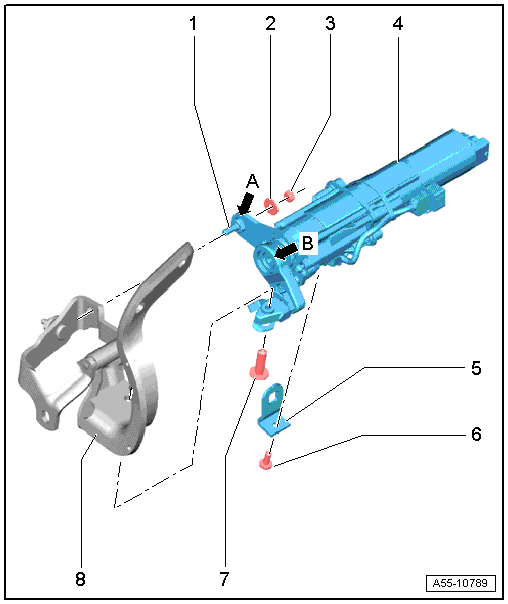
1 - Hex Head Eccentric Bolts
Note
- Upon tightening locking nuts, eccentric bolts are braced in hinge with no play.
- For this reason, you cannot counterhold eccentric bolt hex head with an open-end wrench when tightening locking nuts.
- When removing drive unit, this tension is released with a small turn to the right on eccentric bolt hex head, after you have loosened locking nuts.
2 - Washer
3 - Lock Nut
- Before removing drive unit, loosen lock nuts on eccentric bolts.
- Release eccentric bolt tension in hinge arm by rotating hex head to right, if necessary.
- Self-locking
- 6 Nm
4 - Rear Lid Motor 2 -V445-
- When installing, insert sideways with socket -arrow B- and loose eccentric bolts -arrow A- in hinge.
Note
Drive unit socket must fit flat against hinge axle collar.
- The drive unit arm then moves correctly on the rear lid hinge arm -8-.
- Tighten the screw -6- to the tightening specification to attach the drive unit to the bracket -5-.
- Tighten the locking nuts -3- to the tightening specification
- Tighten the bolt -7- to the tightening specification.
5 - Bracket
Note
- Bracket is positioned with a device in factory and should not be adjusted.
- If bracket must be replaced, for example, when doing repairs after an accident, proceed as follows.
6 - Bolt
- 8 Nm
7 - Bolt
- 21 Nm
- Self-threading
8 - Lid Hinge
- Removing and installing. Refer to → Chapter "Hinges, Removing and Installing, Avant".
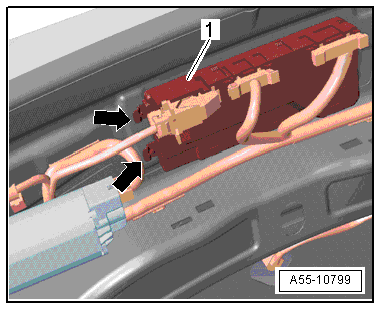
Rear Lid Control Module -J605-, Removing and Installing, Sedan
Removing
- Remove the luggage compartment side trim panel. Refer to → Body Interior; Rep. Gr.70; Luggage Compartment Trim Panels; Luggage Compartment Side Trim Panel, Removing and Installing.
- Disconnect the connectors from the control module.
- Open the retainers -arrows- and remove the control module -1- to the rear.
Installing
Install in reverse order of removal. Note the following:
- Insert the control module into the bracket and then slide it forward until it clicks into place.
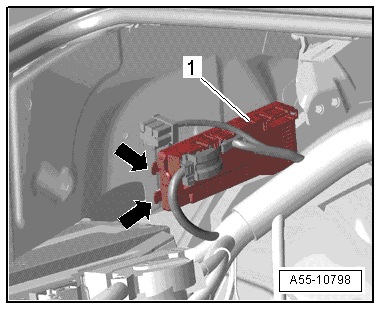
Rear Lid Control Module -J605-, Removing and Installing, Avant
Removing
- Remove the rear roof trim panel. Refer to → Body Interior; Rep. Gr.70; Roof Trim Panels; Roof End Strip, Removing and Installing.
- Disconnect electrical connectors.
- Open the retainers -arrows- and remove the control module -1- to the side.
Installing
Install in reverse order of removal. Note the following:
- Insert the control module into the bracket and then slide it forward until it clicks into place.