Audi A6 Typ 4G: Air Cushion for Lumbar Support, Removing and Installing
Removing
 WARNING
- Follow all Safety Precautions when working with pyrotechnic components. Refer to → Chapter "Pyrotechnic Components Safety Precautions".
- Before handling pyrotechnic components (for example, disconnecting the connector), the person handling it must "discharge static electricity". This can be done by touching the door striker, for example.
- Remove the Multi-contour seat. Refer to → Chapter "Rear Seat Backrest, Removing and Installing, Multi-contour Seat".
- Remove backrest cushion together with backrest cover. Refer to → Chapter "Cover and Cushion, Removing and Installing, Multi-contour Seat".
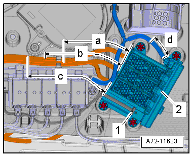
- Mark the pneumatic lines at the separation points with a permanent marker.
- Disconnect pneumatic lines to the lumbar support air cushions at the following points. Refer to → Chapter "Pneumatic Lines, Disconnecting and Connecting".
- -a- = 110 mm
- -b- = 120 mm
- -c- = 130 mm
 Note
Note
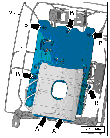
Ignore items -1, 2 and d-.
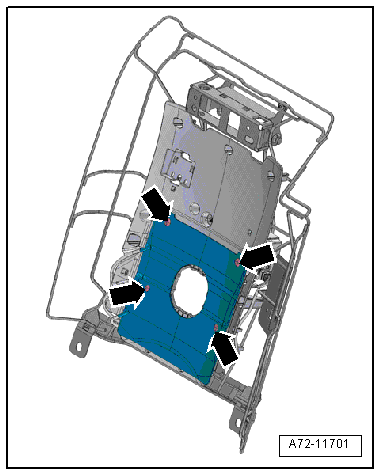
- Remove the expanding rivets -arrows- and remove the air cushion.
Installing
- Cut the pneumatic lines for the new air cushion according to the design of the old air cushion.
- Connect the pneumatic lines. Refer to → Chapter "Pneumatic Lines, Disconnecting and Connecting".
WARNING
- Follow all Safety Precautions when working with pyrotechnic components. Refer to → Chapter "Pyrotechnic Components Safety Precautions".
- Before handling pyrotechnic components (for example, connecting the connector), the person handling it must "discharge static electricity". This can be done by touching the door striker, for example.
- Observe all measures when installing the Multi-contour seat. Refer to → Chapter "Rear Seat Backrest, Removing and Installing, Multi-contour Seat".
Install in reverse order of removal.
Installation notes, for example tightening specifications, replacing components. Refer to → Chapter "Overview - Pneumatic System, Module Carrier/Air Cushion/Lumbar Support".
Valve Block 1 in Driver Side Rear Seat -N479-/Valve Block 1 in Passenger Side Rear Seat -N481-, Removing and Installing
Removing
WARNING
- Follow all Safety Precautions when working with pyrotechnic components. Refer to → Chapter "Pyrotechnic Components Safety Precautions".
- Before handling pyrotechnic components (for example, disconnecting the connector), the person handling it must "discharge static electricity". This can be done by touching the door striker, for example.
- Remove the Multi-contour seat. Refer to → Chapter "Rear Seat Backrest, Removing and Installing, Multi-contour Seat".
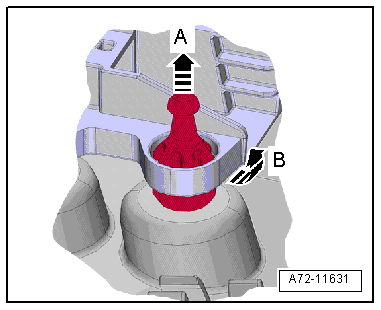
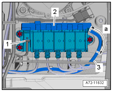
- Pull the rubber buffer lengthwise -arrow A-.
- Remove the valve block from the rubber buffer -arrow B- simultaneously.
- Disconnect the connector -1-.
- For reinstallation, mark pneumatic lines at the separating point with a waterproof permanent marker.
- Disconnect pneumatic lines to the lumbar support air cushions at the following points. Refer to → Chapter "Pneumatic Lines, Disconnecting and Connecting".
- -a- = 110 mm
- -b- = 120 mm
- -c- = 130 mm
- Disconnect the pneumatic line to the compressor at the following locations. Refer to → Chapter "Pneumatic Lines, Disconnecting and Connecting".
- -d- = 30 mm
Installing
- Cut the pneumatic lines for the new valve block according to the design of the old valve block.
- Connect the pneumatic lines. Refer to → Chapter "Pneumatic Lines, Disconnecting and Connecting".
WARNING
- Follow all Safety Precautions when working with pyrotechnic components. Refer to → Chapter "Pyrotechnic Components Safety Precautions".
- Before handling pyrotechnic components (for example, connecting the connector), the person handling it must "discharge static electricity". This can be done by touching the door striker, for example.
- Observe all measures when installing the Multi-contour seat. Refer to → Chapter "Rear Seat Backrest, Removing and Installing, Multi-contour Seat".
Install in reverse order of removal.
Installation notes, for example tightening specifications, replacing components. Refer to → Chapter "Overview - Pneumatic System, Module Carrier/Air Cushion/Lumbar Support".
Module Carrier, Removing and Installing
Removing
WARNING
- Follow all Safety Precautions when working with pyrotechnic components. Refer to → Chapter "Pyrotechnic Components Safety Precautions".
- Before handling pyrotechnic components (for example, disconnecting the connector), the person handling it must "discharge static electricity". This can be done by touching the door striker, for example.
- Remove the Multi-contour seat. Refer to → Chapter "Rear Seat Backrest, Removing and Installing, Multi-contour Seat".
- Remove backrest cushion together with backrest cover. Refer to → Chapter "Cover and Cushion, Removing and Installing, Multi-contour Seat".
- Free up the wiring harness from the lower seat frame.
- Remove the bolts -A arrows-.
- Unclip and remove the module carrier for the lumbar support -1- from the lower seat frame -2--arrows B-.
If only the module carrier is simply replaced, it is sufficient to install the air cushion for the lumbar support with valve blocks and control module for Multi-contour seat with the pneumatic lines:
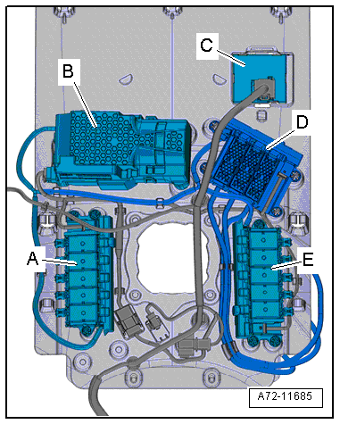
- Remove the control module -C- for the seat adjustment. Refer to → Chapter "Seat Adjustment Control Module, Removing and Installing, Multi-contour Seat".
- Unclip and free up the pneumatic lines and the wires from the module carrier for the lumbar support.
- Remove the valve block -D- with the air cushion for the lumbar support. Refer to → Chapter "Air Cushion for Lumbar Support, Removing and Installing" and → Chapter "Valve Block 1 in Driver Side Rear Seat -N479-/Valve Block 1 in Passenger Side Rear Seat -N481-, Removing and Installing".
- Remove the valve block -A and E- for the massage mat. Refer to → Chapter "Massage Mat Valve Block, Removing and Installing".
- Remove the compressor -B- for the Multi-contour seat. Refer to → Chapter "Compressor with Multi-contour Seat Control Module, Removing and Installing".
Installing
- Route the pneumatic lines and wires as illustrated in the picture.
- Connect the pneumatic lines and give them a push again and then a final tug to see whether the coupling is locked in correctly.
WARNING
- Follow all Safety Precautions when working with pyrotechnic components. Refer to → Chapter "Pyrotechnic Components Safety Precautions".
- Before handling pyrotechnic components (for example, connecting the connector), the person handling it must "discharge static electricity". This can be done by touching the door striker, for example.
- Observe all measures when installing the Multi-contour seat. Refer to → Chapter "Rear Seat Backrest, Removing and Installing, Multi-contour Seat".
Install in reverse order of removal.
Installation notes, for example tightening specifications, replacing components. Refer to → Chapter "Overview - Pneumatic System, Module Carrier/Air Cushion/Lumbar Support".
Massage Mat, Removing and Installing
Removing
WARNING
- Follow all Safety Precautions when working with pyrotechnic components. Refer to → Chapter "Pyrotechnic Components Safety Precautions".
- Before handling pyrotechnic components (for example, disconnecting the connector), the person handling it must "discharge static electricity". This can be done by touching the door striker, for example.
- Remove the Multi-contour seat. Refer to → Chapter "Rear Seat Backrest, Removing and Installing, Multi-contour Seat".
- Remove backrest cushion together with backrest cover. Refer to → Chapter "Cover and Cushion, Removing and Installing, Multi-contour Seat".
- Before disconnecting, mark the pneumatic line assignments to the connections at the valve block using a waterproof permanent marker.
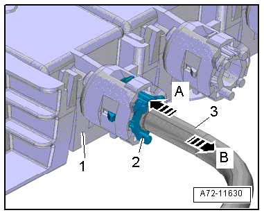
- Press the release ring -2- towards the valve block -1--arrow A- and simultaneously pull on the pneumatic line -arrow B- to release and remove the pneumatic line -3-.
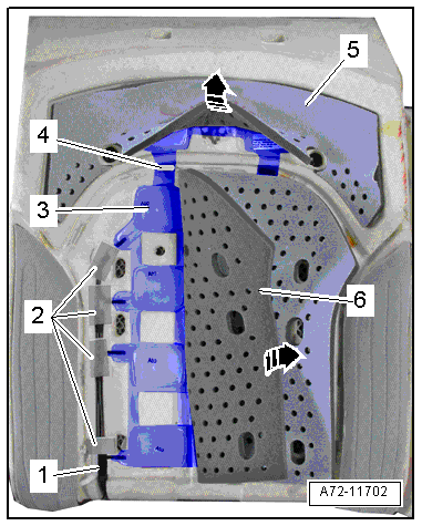
- Carefully loosen the air guide mats -5 and 6- from the bonding and pull back -arrows-.
- loosen the clip -4-.
- Loosen the pneumatic lines -1- from the bonding -2- and free them up.
- Remove the massage mat -3- from the backrest cushion.
Installing
- Route the pneumatic lines in the backrest cushion and connect them to the valve block.
- Connect the pneumatic lines and give them a push again and then a final tug to see whether the coupling is locked in correctly.
- Attach the bonding with double adhesive tape in the same location it was in when it was removed.
WARNING
- Follow all Safety Precautions when working with pyrotechnic components. Refer to → Chapter "Pyrotechnic Components Safety Precautions".
- Before handling pyrotechnic components (for example, connecting the connector), the person handling it must "discharge static electricity". This can be done by touching the door striker, for example.
- Observe all measures when installing the Multi-contour seat. Refer to → Chapter "Rear Seat Backrest, Removing and Installing, Multi-contour Seat".
Install in reverse order of removal.
Installation notes, for example tightening specifications, replacing components. Refer to → Chapter "Overview - Pneumatic System, Massage Mat".
Massage Mat Valve Block, Removing and Installing
Removing
WARNING
- Follow all Safety Precautions when working with pyrotechnic components. Refer to → Chapter "Pyrotechnic Components Safety Precautions".
- Before handling pyrotechnic components (for example, disconnecting the connector), the person handling it must "discharge static electricity". This can be done by touching the door striker, for example.
- Remove the Multi-contour seat. Refer to → Chapter "Rear Seat Backrest, Removing and Installing, Multi-contour Seat".
- Before disconnecting, mark the pneumatic line assignments to the connections at the valve block using a waterproof permanent marker.
- Press the release ring -2- towards the valve block -1- in direction of -arrow A- and simultaneously pull on the pneumatic line in direction of -arrow B- to release and remove the pneumatic line -3-.
- Pull the rubber buffer lengthwise in direction of -arrow A-.
- Remove the valve block from the rubber buffer -arrow B- simultaneously.
- Disconnect the connector -1- from the valve block -2-.
- Disconnect the pneumatic line -3- to the compressor at the following locations. Refer to → Chapter "Pneumatic Lines, Disconnecting and Connecting".
- -a- = 40 mm
Installing
- Cut the pneumatic lines to the compressor on the valve block according to the design of the old valve block.
- Connect the pneumatic line. Refer to → Chapter "Pneumatic Lines, Disconnecting and Connecting".
- Connect the pneumatic lines to the massage mat air cushions on the valve block and give them a push again and then a final tug to see whether the coupling is locked in correctly.
WARNING
- Follow all Safety Precautions when working with pyrotechnic components. Refer to → Chapter "Pyrotechnic Components Safety Precautions".
- Before handling pyrotechnic components (for example, connecting the connector), the person handling it must "discharge static electricity". This can be done by touching the door striker, for example.
- Observe all measures when installing the Multi-contour seat. Refer to → Chapter "Rear Seat Backrest, Removing and Installing, Multi-contour Seat".
Install in reverse order of removal.
Installation notes, for example tightening specifications, replacing components. Refer to → Chapter "Overview - Pneumatic System, Massage Mat".
Special Tools
Special tools and workshop equipment required
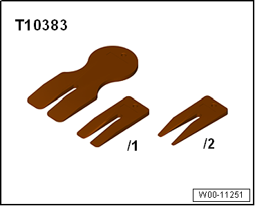
- Wedge Set -T10383-
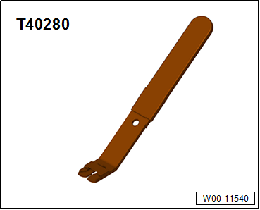
- Omega Clip Tool -T40280-
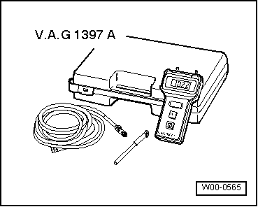
- Turbocharger Tester Kit -VAG1397A-
- Pop Rivet Pliers -VAG1753B-
- Upholstery Clip Pliers -VAG1634-
- Pop Rivet Nut Pliers -VAS5073A-
- Engine And Transmission Holder -VAS6095-
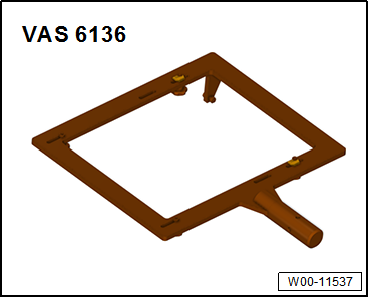
- Engine/Transmission Holder - Seat Repair Fixture -VAS6136-
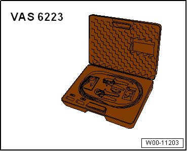
- Fiber-Optic Repair Set - Connector Protective Caps -VAS6223/9- from the Fiber Optic Repair Set -VAS6223-
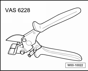
- Hose Cutting Pliers -VAS6228-
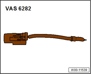
- Airbag Lockout Adapter -VAS6282-
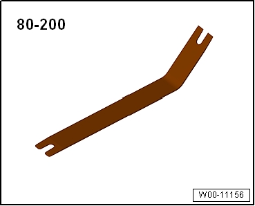
- Pry Lever -80-200-
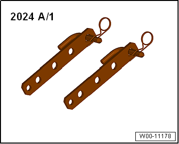
- Engine Sling - Engine Bracket -2024A/1-
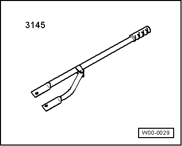
- Driveshaft Handle - 3145-
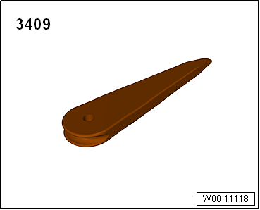
- Trim Removal Wedge -3409-
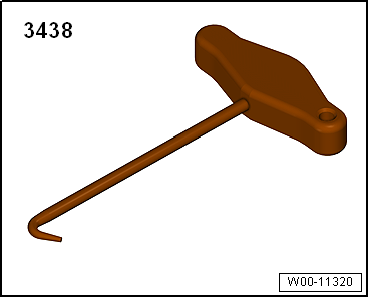
- T-Handle Hook -3438-
- Pneumatic Repair Set -VAS6618A-