Audi A6 Typ 4G: Automatic Transmission Fluid
ATF Level, Checking
Special tools and workshop equipment required
- Vehicle Diagnostic Tester
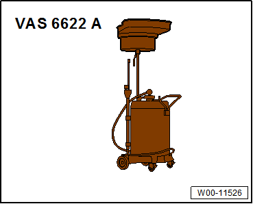
- Used Oil Collection and Extraction Unit -SMN372500-
- Protective eyewear
 Caution
Danger of causing damage to the transmission.
- Only use replacement part ATF for the S tronic transmission 0B5.
- Allocation, refer to the Parts Catalog.
- Using other types of ATF can result in the malfunctions or transmission failure.
- The ATF filler tool must be clean and the ATF must not be mixed with any other oils.
 Note
Note
- Read the ATF temperature on the Vehicle Diagnostic Tester.
- The ATF level will vary depending on the temperature of the ATF.
- It is possible to overfill the ATF if the level is checked when the temperature is too low.
- It is possible to underfill the ATF if the level is checked when the temperature is too high.
- Overfilling or underfilling will influence the function of the transmission.
Test Conditions
- The transmission must not be in the emergency running
- Move vehicle onto a four-pillar workshop hoist or over a work pit so that it is absolutely horizontal.
- The selector level is in "P".
- The parking brake button should be activated to close the electro-mechanical parking brake.
- Intake hose/-hoses of an exhaust extraction system connected.
- The A/C and the heater are off.
- Vehicle Diagnostic Tester is connected.
- The ATF temperature should not be higher than 30 ºC (86 ºF) at the beginning of the test, because during the test the ATF temperature will raise.
ATF Level, Checking
- Select the following menu items in Functions/Component selection "Guided Fault Finding" on the Vehicle Diagnostic Tester:
- Drive train
- 0B5 - Transmission
- 01-OBD-capable systems
- 02-transmission electronics
- 02-Transmission electronics, functions
- 02-Measured values
- Select transmission fluid temperature from the list.
- Check the ATF temperature.
 Caution
Danger of causing damage to the transmission.
- Engine must not be started if only a small amount or no ATF is in the transmission after repair work or after significant ATF loss.
- In this case, pre-filling is necessary, refer to → Chapter "ATF, Draining and Filling".
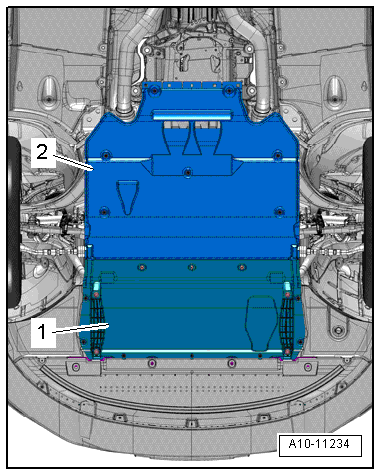
- Remove the rear noise insulation -2-, refer to → Body Exterior; Rep. Gr.66; Noise Insulation; Noise Insulation, Removing and Installing.
- Start the engine with the selector lever in "P".
- While pressing the brake pedal and with the vehicle idling, shift through all the selector lever positions ("P", "R", "N", "D", "S") leaving each position engaged for at least 10 seconds.
- Move the selector lever into "N".
- Move the selector lever into "P".
- Run the engine at idle.
- Place the Used Oil Collection and Extraction Unit -SMN372500- under the transmission.
 WARNING
Danger of eye injury.
Wear protective eyewear.
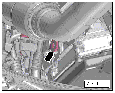
- When ATF temperature of 30 ºC (86 ºF) is reached, unscrew ATF inspection plug -arrow-.
- ATF level is correct when at an ATF temperature between 30 º and 50 ºC (86 and 122 ºF) a small amount of fluid drips out of the inspection hole. If this is not the case, add ATF, refer to → Chapter "ATF, Draining and Filling".
 Note
Note
ATF inspection opening must be closed again by 50 ℃ at the latest.
- Tighten the ATF inspection plug.
ATF, Draining and Filling
Special tools and workshop equipment required
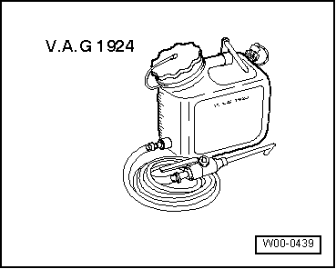
- ATF Filler Tool -VAG1924-
- Used Oil Collection and Extraction Unit -SMN372500-
- Protective eyewear
 Caution
Danger of causing damage to the transmission.
Do not start the engine when there is no ATF in the transmission.
ATF, Draining
- The engine is off.
- Move vehicle onto a four-pillar workshop hoist or over a work pit so that it is absolutely horizontal.
- The selector level is in "P".
- The parking brake button should be activated to close the electro-mechanical parking brake.
- Remove the rear noise insulation -2-, refer to → Body Exterior; Rep. Gr.66; Noise Insulation; Noise Insulation, Removing and Installing.

- Place the Used Oil Collection and Extraction Unit -SMN372500- under the transmission.
 WARNING
Danger of eye injury.
Wear protective eyewear.
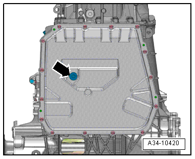
- Remove the ATF drain plug -arrow- and let the ATF drain out.
- Replace the seal for the ATF drain plug.
- Tighten the ATF drain plug.
 Note
Note
When the ATF fluid is changed, the ATF filter should always be replaced, refer to → Chapter "ATF Filter, Removing and Installing".
Fill the transmission with ATF.
 Caution
Danger of causing damage to the transmission.
- Only use replacement part ATF for the S tronic transmission 0B5.
- Allocation, refer to the Parts Catalog.
- Using other types of ATF can result in the malfunctions or transmission failure.
- The ATF filler tool must be clean and the ATF must not be mixed with any other oils.
- Engine must not be started if only a small amount or no ATF is in the transmission after repair work or after significant ATF loss.
- Fill the ATF Filler Tool -VAG1924- reservoir with ATF for "S tronic transmission 0B5"; ATF specification, refer to the Parts Catalog.
- Secure reservoir of ATF Filler Tool -VAG1924- as high as possible on vehicle.
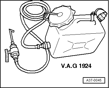
- Remove the ATF check plug -arrow-.
- Engage the filler hook from the ATF Filler Tool -VAG1924- into the ATF inspection opening.
- Add ATF using ATF Filler Tool -VAG1924- until ATF drips from the check hole.
- Move the selector lever into "P".
- Start the engine, wait 20 seconds and then turn it off.
- Add ATF using ATF Filler Tool -VAG1924- until ATF drips from the check hole.
- Start the engine and let it run in idle.
- Continue to add ATF using ATF Filler Tool -VAG1924- until ATF drips from the check hole.
- Install the ATF inspection plug.
- Check the ATF level, refer to → Chapter "ATF Level, Checking".

Special Tools
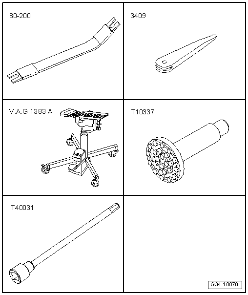
Special tools and workshop equipment required
- Pry lever -80-200-
- Trim Removal Wedge -3409-
- Engine and Gearbox Jack -VAS6931-
- Engine/Gearbox Jack - Gearbox Support -T10337-
- Socket And Key -T40031-
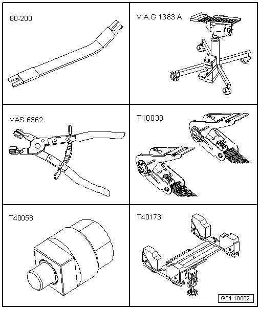
- Pry lever -80-200-
- Engine and Gearbox Jack -VAS6931-
- Hose Clip Pliers -VAS6362-
- Tensioning Strap -T10038-
- Crankshaft Socket -T40058-
- Gearbox Support -T40173-
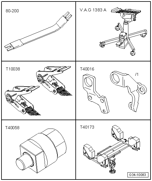
- Pry lever -80-200-
- Engine and Gearbox Jack -VAS6931-
- Tensioning Strap -T10038-
- Motor Transport Loop -T40016-
- Crankshaft Socket -T40058-
- Gearbox Support -T40173-
- M8 x 20 bolt
- Used Oil Collection and Extraction Unit -SMN372500-
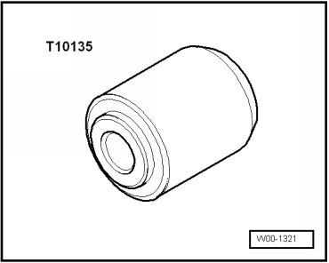
- Seal Installer - Selector Shaft -T10135-
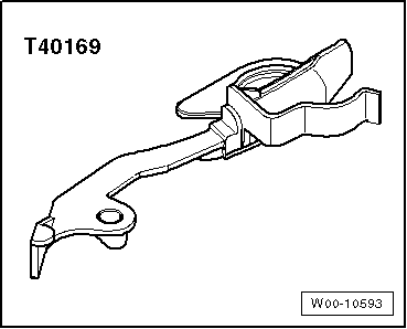
- Clutch Module Assembly Aid -T40169-
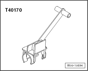
- Clutch Module Transportation Lock -T40170-
- Crankshaft Turning Tool -T40272-
- ATF Filler Tool -VAG1924-
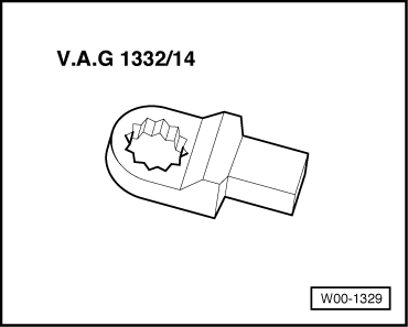
- Torque Wrench 1332 Insert - Ring Wrench - 16mm -VAG1332/14-
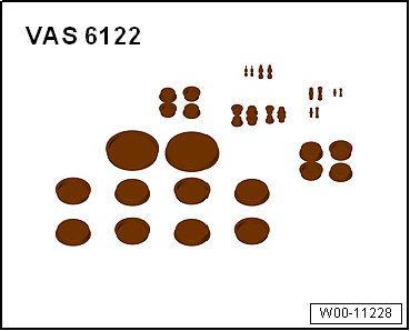
- Engine Bung Set -VAS6122-
