Audi A6 Typ 4G: Shaft Seal for Flange/Propshaft, Replacing
Rear Final Drive 0BF - Flange/Driveshaft Shaft Seal, Replacing
Special tools and workshop equipment required
- Puller - Multiple Use -VW391-
- Puller - Unit Injector -T10055-
- -2-Puller - Unit Injector - Adapter 2 -T10055/2-
- Two M 8 x 30 Bolts
- Seal Installer - Hollow Shaft -T10380-
- Seal Installer - Input Shaft -T40222-
- Seal Installer - Input Shaft - Guide Sleeve -T40222/1-
- Sealing Grease -G 052 128 A1-
- Inductive Heater -VAS6414-
or
- Commercially Available Hot Plate
and
- Digital Thermometer -VAS6519-
Removing
- Rear final drive installed
- Follow the general repair information. Refer to → Chapter "General Repair Information".
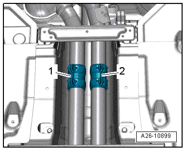
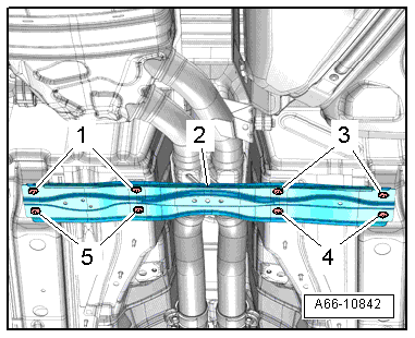
- Disconnect the exhaust system at the clamping sleeves -1- and -2-.
- Remove the rear section of the exhaust system.
 Note
Note
A second technician is needed to help remove the rear section of the exhaust system.
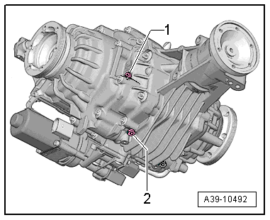
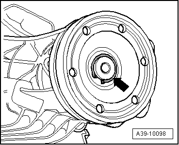
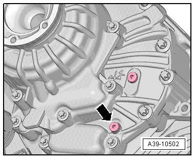
- Open the gear oil drain plug -2- and allow approximately 300 ml of gear oil to drain out.
- Insert the new drain plug -2- and tighten. Tightening specification -item 16-.
- Remove the driveshaft from the rear final drive. Refer to → Chapter "Driveshaft, Removing and Installing from Rear Final Drive".
Audi A8
- Guide the driveshaft between the fuel tank and the subframe downward toward the rear and attach it on the side.
Audi A4, A5 Coupe/Sportback/Cabrio
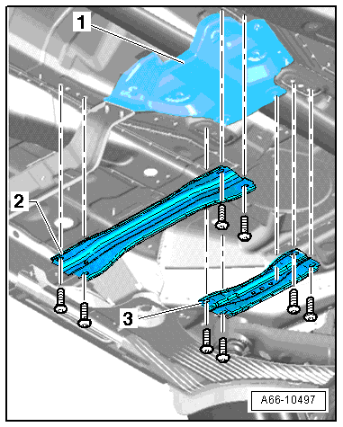
- Remove the front crossmember -2-.
- Remove the rear crossmember -3- and the heat shield -1-.
Audi A6 and A7
- Remove the crossbrace -2-. Refer to →Body Exterior; Rep. Gr.66.
Audi A4, A5 Coupe/Sportback/Cabrio, A6, A7
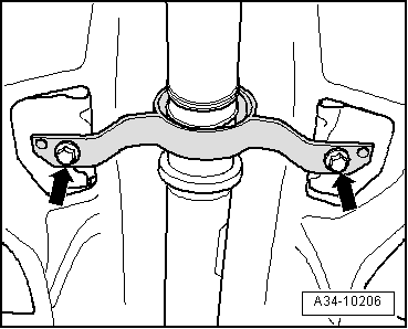
- Remove the bolts -arrows- for the driveshaft intermediate bearing.
- Lower the driveshaft at the intermediate bearing.
- Guide the driveshaft between the fuel tank and the subframe downward and toward the rear while doing this.
- Install the intermediate bearing bolts -arrows- by hand.
- Tie the driveshaft to the side.
Continuation for All Vehicles
- Remove the High Temperature Grease in the flange/driveshaft.
- Remove the circlip -arrow-.
- Mark the position of the flange/driveshaft -B- on the pinion -A--arrow-.
Note
- This marking -arrow- is needed so the colored dot -C- on the outer flange remains in its original position.
- This ensures the imbalance in the rear final drive will be as small as possible.
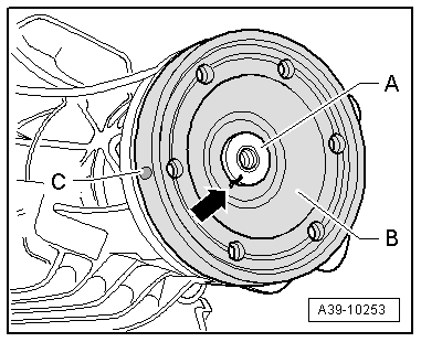
- Install the Two M8 x 33 bolts-arrow- in the flange.
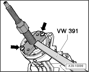
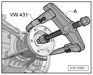
- Remove the flange/driveshaft with the Puller - Multiple Use -VW391-.
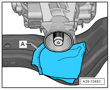
- Lay a super absorbent cloth -A- under the final drive on the subframe.
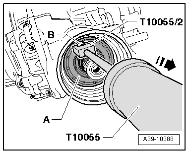
- Knock through the metal ledge of the shaft seal -A-, for example, with a scriber -B- direction of the -arrow-.
- Then install a bolt -arrow- in this shaft seal opening -A-.
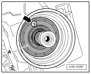
- Remove the flange/driveshaft seal -A- in the direction of -arrow-.
-B- bolt
Installing
Install in reverse order of removal. Pay attention to the following:
- Fill the space between the sealing/dust lip halfway with Sealing Grease -G 052 128 A1-.
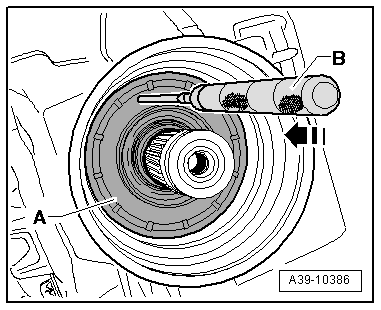
- Place the new shaft seal -A- on the Seal Installer - Input Shaft - Guide Sleeve -T40222/1-.
Note
Make sure the shaft seal spring is in its installation position behind the sealing lip.
- Coat outer edge of the seal with gear oil.
- Push the Seal Installer - Input Shaft - Guide Sleeve -T40222/1- and the shaft seal -A- onto the pinion -B-.
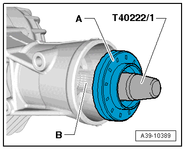
- Install the shaft seal all the way. Be careful not to bend it.
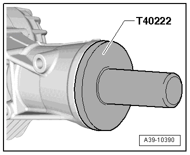
- Warm the flange/driveshaft -B- with a Inductive Heater -VAS6414- or a Heating Plate to 115 ºC (239 ºF).
 WARNING
- Wear safety gloves.
- If using a Heating Plate the temperature must be observed using a Digital Thermometer -VAS6519-.
- Position the flange/driveshaft -B- on the pinion -A- so that the marking -arrow- lines up.
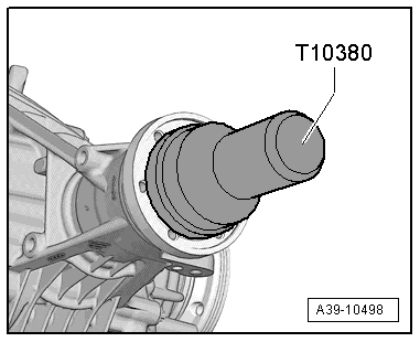
- Install the flange/driveshaft with the Seal Installer - Hollow Shaft -T10380-.
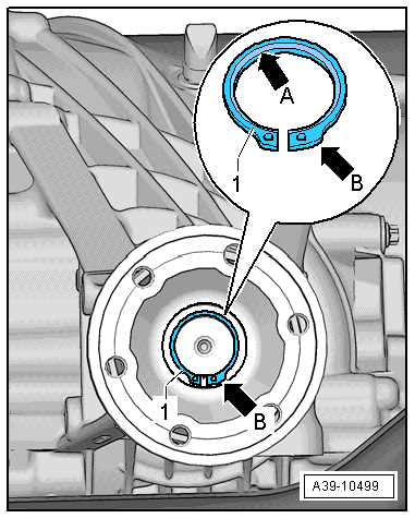
Install the circlip -1- as follows:
- Always replace the circlip -1-.
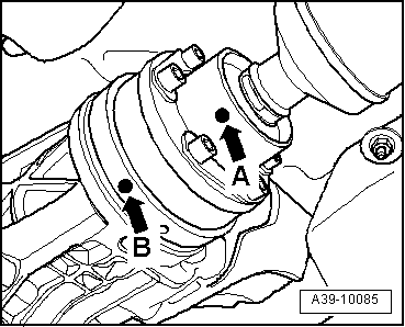
- The bevel on the inner diameter of the circlip -arrow A- faces out, toward the drive axle.
- The wide tab on the circlip -arrow B- must be on the right side, as illustrated.
- Measure the thickness of the old circlip -1-.
- Install a new circlip -1- having the same thickness as the old one. Refer to the Part Catalog.
- Install the new circlip -1-.
Note
- A new circlip -arrow- must be selected when replacing the flange/driveshaft.
- For this, determine and insert the thickest circlip -arrow- that can still be installed in the groove. Refer to the Parts Catalog for the part number.
- Fill the rear final drive gear oil 0BF. Refer to → Chapter "Gear Oil in Rear Final Drive 0BF, Filling".
- Install the driveshaft on the rear final drive.
Audi A4, A5 Coupe/Sportback/Cabrio, A6, A7
- Attach the driveshaft center support to the body free of tension. Tightening specification -item 9-.
- Install the heat shield and the crossmember.
Continuation for All Vehicles
- Install the rear section of the exhaust system.
Rear Final Drive 0BE - Replacing, Flange/Driveshaft Shaft Seal
Special tools and workshop equipment required
- Press Piece - Multiple Use -VW431-
- Puller - Unit Injector -T10055-
- Puller - Unit Injector - Adapter 2 -T10055/2-
- Seal Installer - Hollow Shaft -T10380-
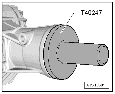
- Seal Installer - Propshaft -T40247-
- Seal Installer - Propshaft - Guide Sleeve -T40247/1-
- -1-Puller - Kukko 2-Arm - 70-180mm -20/10-
- Inductive Heater -VAS6414-
or
- Commercially Available Hot Plate
and
- Digital Thermometer -VAS6519-
- Drip Tray
- Sealing Grease -G 052 128 A1-
Removing
- Rear final drive installed
- Disconnect the exhaust system at the clamping sleeves -1 and 2-.
- Remove the rear section of the exhaust system.
Note
A second technician is needed to help remove the rear section of the exhaust system.
- Open the gear oil drain plug -arrow- and allow approximately 300 ml of gear oil to drain out.
- Insert the new drain plug -arrow- and tighten. Tightening specification -item 16-.
- Remove the driveshaft from the rear final drive. Refer to → Chapter "Driveshaft, Removing and Installing from Rear Final Drive".
- Guide the driveshaft between the fuel tank and the subframe downward toward the rear and attach it on the side.
- Remove the High Temperature Grease in the flange/driveshaft.
- Remove the circlip -arrow-.
- Mark the position of the flange/driveshaft -B- on the pinion -A--arrow-.
Note
- This marking -arrow- is needed so the colored dot -C- on the outer flange remains in its original position.
- This ensures the imbalance in the rear final drive will be as small as possible.
- Remove the flange/driveshaft.
A - For example the Puller - Kukko 2-Arm - 70-180mm -20/10-
- Lay a super absorbent cloth -A- under the final drive on the subframe.
- Knock through the metal ledge of the shaft seal -A-, for example, with a scriber -B- direction of the -arrow-.
- Then install a bolt -arrow- in this shaft seal opening -A-.
- Remove the flange/driveshaft seal -A- in the direction of -arrow-.
B - Bolt
Installing
Install in reverse order of removal. Pay attention to the following:
- Fill the space between the sealing/dust lip halfway with Sealing Grease -G 052 128 A1-.
- Coat outer edge of the seal with gear oil.
- Place the new shaft seal -A- on the Seal Installer - Propshaft - Guide Sleeve -T40247/1-.
Note
Make sure the shaft seal spring is in its installation position behind the sealing lip.
- Push the Seal Installer - Propshaft - Guide Sleeve -T40247/1- and the shaft seal -A- onto the pinion -B-.

- Install the shaft seal all the way. Be careful not to bend it.
- Warm the flange/driveshaft -B- with a Inductive Heater -VAS6414- or a Heating Plate to 115 ºC (239 ºF).
WARNING
- Wear safety gloves.
- If using a Heating Plate the temperature must be observed using a Digital Thermometer -VAS6519-.
- Position the flange/driveshaft -B- on the pinion -A- so that the marking -arrow- lines up.
- Install the flange/driveshaft with the Seal Installer - Hollow Shaft -T10380-.
Install the circlip -1- as follows:
- Always replace the circlip -1-.
- The bevel on the inner diameter of the circlip -arrow A- faces out, toward the driveshaft.
- The wide tab on the circlip -arrow B- must be on the right side, as illustrated.
- Measure the thickness of the old circlip -1-.
- Install a new circlip -1- having the same thickness as the old one. Refer to the Part Catalog.
- Install the new circlip -1-.
Note
- A new circlip -arrow- must be selected when replacing the flange/driveshaft.
- For this, determine and insert the thickest circlip -arrow- that can still be installed in the groove. Refer to the Parts Catalog for the part number.
- Fill with gear oil in the rear final drive 0BE. Refer to → Chapter "Gear Oil in Rear Final Drive 0BE, Filling".
- Install the driveshaft on the rear final drive.
- Install the rear section of the exhaust system.
Flange/Driveshaft Seal, Replacing
Special tools and workshop equipment required
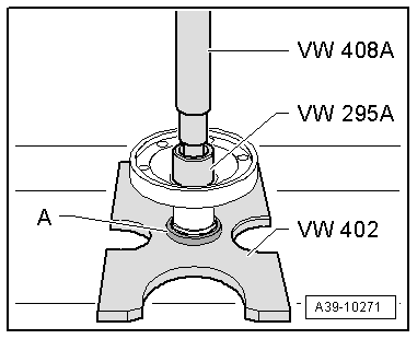
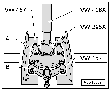
- Bearing/Bushing Installer - Multiple Use -VW295A-
- Press Plate -VW402-
- Press Piece - Rod -VW408A-
- Support Channels -VW457-
- Separating tool 22 to 75 mm, such as Puller - Kukko Quick Action Separating Tool - 12-75mm -17/1-
Remove the Ring -A- from the Flange/Driveshaft.
B - Separating Tool - 12-75mm, such as Puller - Kukko Quick Action Separating Tool - 12-75mm -17/1-
Installation Location of the Protective Ring -A- on the Flange/Driveshaft
- The ridge -arrow 1- on the protective ring -A- must fit into the groove -arrow 2- on the flange -B-. The smaller outer circumference -arrow 3- faces the flange.
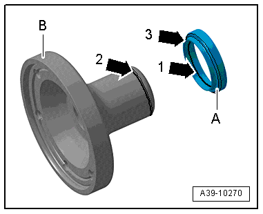
Install the Protective Ring -A- onto the Flange/Driveshaft.
- The protective ring -A- must fit into the groove all around the flange. Refer to → Fig. "Installation Location of the Protective Ring -A- on the Flange/Driveshaft".