Audi A6 Typ 4G: Battery Charger -VAS5906-
 WARNING
Risk of injury. Follow all warning messages and safety precautions. Refer to → Chapter "Warnings and Safety Precautions".
 WARNING
Do not check or charge a Battery -A- when the visual indicator has "no color or is bright yellow". Jump starting must not be used!
There is a risk of explosion during testing, charging or jump starting.
These Batteries -A- must be replaced.
 Note
Note
Observe the Battery Charger -VAS5906- Operating Instructions.
- Battery Charger -VAS5906- device description. Refer to → Chapter "Battery Charger -VAS5906- Device Description".
- Charge the Battery -A-. Refer to → Chapter "Battery, Charging with Battery Charger -VAS5906-".
Battery Charger -VAS5906- Device Description
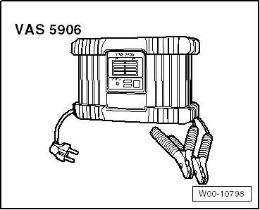
Battery Charger -VAS5906-
The Battery Charger -VAS5906- was developed especially for charging the vehicle electrical system while the vehicle is on display.
It supplies for automatic charging of 3 - 300 Ah for starter batteries.
The 14.4 V maximum charging voltage is not exceeded. All electrical consumers will be supported up to 30 A by the support charging.
After the battery -A- is completely charged, the Battery Charger -VAS5906- switches into the maintenance charging for long-term operation.
The Battery Charger -VAS5906- starts automatically and does not need any adjustments. Only the charging terminals and the network cable need to be connected.
For more information. Refer to the Battery Charger -VAS5906- Operating Instructions.

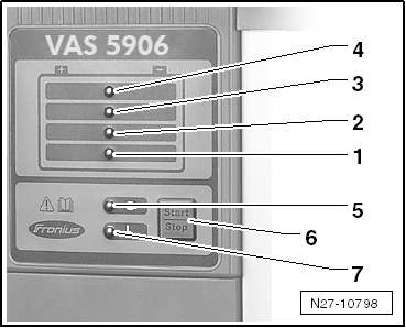
Control Field Overview
1 - 25% charge display
2 - 50% charge display
3 - 75% charge display
4 - 100% charge display
5 - Ready-to-use display
6 - Pushing the START/STOP and Setup buttons will stop and start the charging process. Enter into the setup menu and select characteristic line type (hold for 10 seconds)
7 - Display malfunction

Battery, Charging with Battery Charger -VAS5906-
 WARNING
Risk of injury. Follow all warning messages and safety precautions. Refer to → Chapter "Warnings and Safety Precautions".
 WARNING
Do not check or charge a Battery -A- when the visual indicator has "no color or is bright yellow". Jump starting must not be used!
There is a risk of explosion during testing, charging or jump starting.
These Batteries -A- must be replaced.
Special tools and workshop equipment required
- Battery Charger -VAS5906-
Procedure
- Place the Battery Charger -VAS5906- in the engine compartment or under the vehicle.
- Connect the Battery Charger -VAS5906- to the power supply.
The Battery Charger -VAS5906- is in idle, the display comes on when it is "ready to be used".
 WARNING
Risk of injury. Follow all warning messages and safety precautions. Refer to → Chapter "Warnings and Safety Precautions".
 Caution
- Turn off the ignition and all electrical equipment.
- Remove the key.
- Connect the red charge terminal (+) to the positive terminal of the Battery -A-.
 Note
Note
On vehicles with a Start/Stop function and an installed Battery Monitoring Control Module -J367-, the black charge terminal (-) must be connected to the body ground. The Start/Stop system will malfunction when it is connected to the Battery -A- negative terminal.
- Connect the black charge terminal (-) to the negative terminal of the Battery -A-/negative connector.
The charging process starts after approximately two seconds.
LEDs show the Battery -A- charge level. When all the lamps are on, the Battery -A- is charged.
When the Battery -A- is completely charged, the Battery Charger -VAS5906- automatically switches to maintenance charging.
 Caution
Sparks can result if the charging terminals are removed too early. End the charging process by pressing the START/STOP button.
Battery -A- Charging, Ending
- Press the START/STOP-button.
- Remove the charging clamps from the battery terminals.
- Disconnect the Battery Charger -VAS5906- from the power.
Solar Battery Maintainer -VAS6102A-
Solar Battery Maintainer -VAS6102A- Device Description
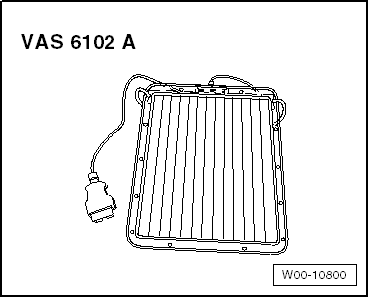
Solar Battery Maintainer -VAS6102A-
The Solar Battery Maintainer -VAS6102A- supports the vehicle electrical system and prevents the Battery -A- from self-discharging.
The Solar Battery Maintainer -VAS6102A- reaches a maximum voltage of 14.3 V and a maximum charge current of 255 mA.
All chargeable lead- and lead gel batteries can be charged with the Solar Battery Maintainer -VAS6102A-.
The Solar Battery Maintainer -VAS6102A- is connected to the diagnostic connection in the vehicle.
The Solar Battery Maintainer -VAS6102A- has a green LED integrated inside the frame which displays the function being performed. The brighter the LED, the higher the charging current.
It is not possible to overcharge the Battery -A- due to the integrated electronics.

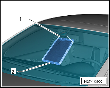
The Solar Battery Maintainer -VAS6102A- is secured on the interior rearview mirror -1-. The bottom rests on the instrument panel -2-.
 Note
Note
The Solar Battery Maintainer -VAS6102A- must not touch the instrument panel completely. Only the bottom edge may be used for support. If it touches completely, the color of the instrument panel could change.

Solar Battery Maintainer -VAS610A- Maintenance Charging
Special tools and workshop equipment required
- Solar Battery Maintainer -VAS6102A-
Procedure
- Secure the Solar Battery Maintainer -VAS6102 A- to the interior rearview mirror -1-.
- Lay the bottom on the instrument panel -2-.
 Note
Note
The Solar Battery Maintainer -VAS6102A- must not touch the instrument panel completely. Only the bottom edge may be used for support. If it touches completely, the color of the instrument panel could change.
- Pull the securing string together so that the Solar Battery Maintainer -VAS6102A- is close to the windshield.
- Connect the connector for the Solar Battery Maintainer -VAS6102A- to the vehicle diagnostic connection. Connecting is the same as with Vehicle Diagnostic Tester.
- Check the Solar Battery Maintainer -VAS6102A- functionality. The green LED must come on.

Severely Discharged Batteries
 WARNING
Risk of injury. Follow all warning messages and safety precautions. Refer to → Chapter "Warnings and Safety Precautions".
A Battery -A- is designated as "severely discharged" if the resting voltage is less than 11.6 V.
 WARNING
Do not check or charge a Battery -A- when the visual indicator has "no color or is bright yellow". Jump starting must not be used!
There is a risk of explosion during testing, charging or jump starting.
These Batteries -A- must be replaced.
 Caution
- Severely discharged Batteries -A- freeze earlier.
- Batteries -A- that have frozen must no longer be used.
 Note
Note
- Batteries -A- that have not been used for a long time will discharge by themselves.
- In severely discharged Batteries -A-, the electrolyte consists almost completely of water, because the acid portion has been greatly reduced.
- Severely discharged Batteries -A- become sulfated, meaning all of the plate surfaces of the Batteries -A- harden.
- The sulfation process may be reversed if a severely discharged Battery -A- is recharged immediately.
- If the Battery -A- is not recharged, the plates will continue to harden, and the ability to accept a charge will decrease. This results in reduction of battery performance.
- Severely discharged Batteries -A- in vehicles must be replaced prior to delivery. Pre-existing damage cannot be ruled out.
Procedure
- Check the Battery -A- resting voltage. Refer to → Chapter "Battery, Charging".
- Charge the Battery -A-:
- Battery Charger -VAS5095A-. Refer to → Chapter "Severely Discharged Battery, Charging with Battery Charger -VAS5095A-".
- Battery Charger -VAS5900-. Refer to → Chapter "Severely Discharged Battery, Charging with Battery Charger -VAS5900-".
- Battery Charger -VAS5903-. Refer to → Chapter "Severely Discharged Battery, Charging with Battery Charger -VAS5903-".
- Battery Charger -VAS5906-. Refer to → Chapter "Battery, Charging with Battery Charger -VAS5906-".

