Audi A6 Typ 4G: Battery, Charging
Battery, Preparing for Charging
Procedure
 WARNING
Risk of explosion on discharged battery with "Visual indicator".
If the "Visual indicator" has no color or is light yellow, the battery may not be tested or charged. Jump starting must not be used! There is a risk of explosion during testing, charging or jump starting. The battery must be replaced.
Before the battery charger can be connected, the following preparations are necessary:
 Note
Note
It is recommended that the battery is charged when installed and connected. This is the only way to ensure the charge current is incorporated into the capacity calculation for the Battery Monitoring Control Module -J367-.
- Turn off the ignition and all electrical equipment.
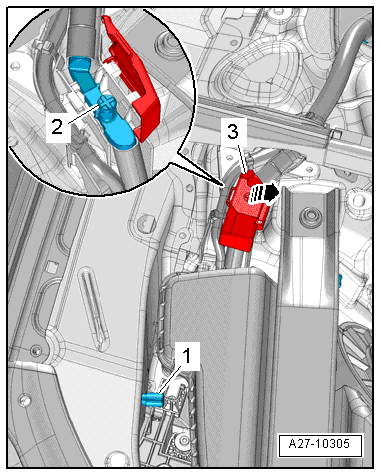
- Release the cover -3- and swivel it to the side in direction of -arrow-.
- Connect the red charging clamp "+" from the battery charger to the positive service terminal -2- and the black charging clamp "-" to the ground service terminal -1-.
- Connect the battery charger electrical system connector and turn on the battery charger. Refer to → Electrical Equipment General Information; Rep. Gr.27; Battery, Charging.
- Leave the hood open while charging the battery.
Battery, Preparing for Support Mode
Procedure
- Release the cover -3- and swivel it to the side in direction of -arrow-.
- Connect the red charging clamp "+" from the battery charger to the positive service terminal -2- and the black charging clamp "-" to the ground service terminal -1-.
- Connect the battery charger electrical system connector and turn on the battery charger. Refer to → Electrical Equipment General Information; Rep. Gr.27; Battery, Charging.
Battery Cut-Out/Battery Interrupt, Removing and Installing
Replace the Battery Interrupt Igniter -N253- if it is faulty or if the Battery Interrupt Igniter -N253- has deployed.
