Audi A6 Typ 4G: Battery Jump Start Terminal
Overview - Battery Jump Start Terminal
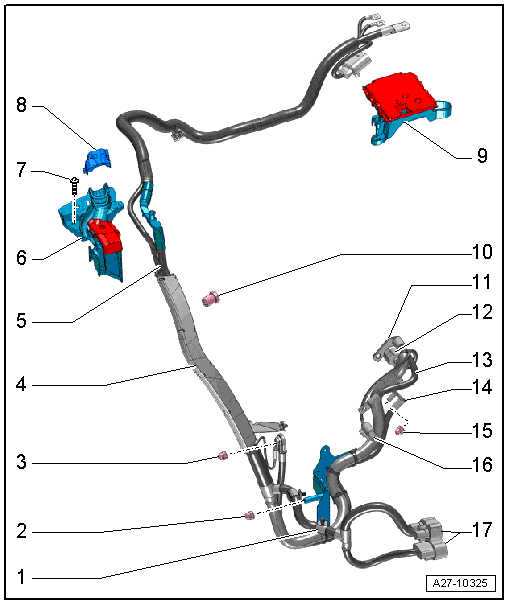
1 - Cable Holder
- Quantity: 2
2 - Nut
- 40 Nm
- For wiring harness bracket
3 - Nut
- Tightening specification. Refer to → Wiring diagrams, Troubleshooting & Component locations.
4 - Wiring Guide
- With holder
5 - Battery Jump Start Terminal -U6-
- Positive service terminal with wiring harness
- Removing and installing. Refer to → Chapter "Battery Jump Start Terminal -U6-, Removing and Installing".
6 - Mount
- For Battery Jump Start Terminal -U6-
- Removing and installing. Refer to → Chapter "Battery Jump Start Terminal -U6- Mount, Removing and Installing".
7 - Screw
- 4 Nm
- Quantity: 2
8 - Cover
- For the wiring harness
9 - Terminal 30 Wire Junction -TV2-
- Overview. Refer to → Chapter "Terminal 30 Wire Junction -TV2-, Removing and Installing".
10 - Remote Start Connection
- 9 Nm
- Negative service terminal
11 - Terminal B+
- To the starter
12 - Connector
- To the starter
13 - Terminal 30/B+
- To the generator
14 - Ground Cable
- On the engine support
15 - Nut
- Tightening specification. Refer to → Wiring diagrams, Troubleshooting & Component locations.
16 - Connector
- To the generator
17 - Connectors
- On the radiator fans
Jump Start Point, Removing and Installing
Battery Jump Start Terminal -U6-, Removing and Installing
Removing
- With the ignition switched off, disconnect the ground cable from the battery. Refer to → Chapter "Battery, Disconnecting and Connecting".
- Remove the right engine mount. Refer to → Rep. Gr.10; Subframe Mount; Engine Mount, Removing and Installing.
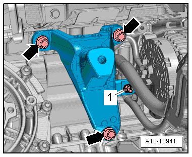
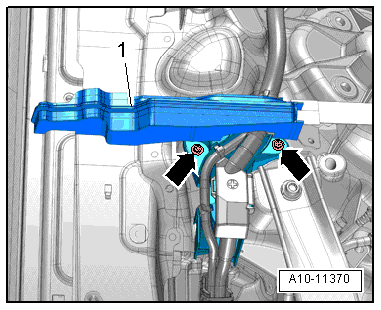
- Remove the nut -1- and free up the ground cable on the engine support.
- Remove the bolts -arrows- and the right engine support.
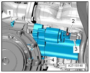
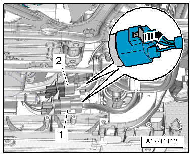
- Press the release down, slide the retainer back and disconnect the connector -3- from the starter.
- Remove the nut -2- and the battery positive wire from the solenoid switch.
 Note
Note
- Ignore -items 1 and 4-.
- Shown on a 3.0L TFSI engine in the illustrations.
- Slide the retainer to the back in direction of -arrow-, push the release down and disconnect the connectors -1- and -2- from the radiator fans.
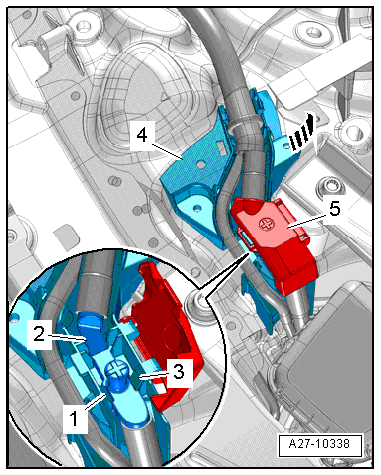
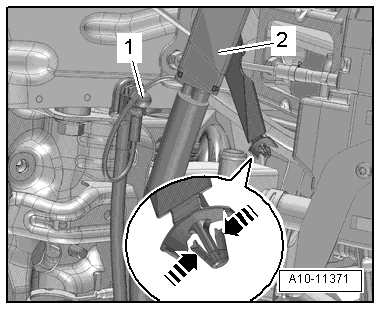
- Release the catches in direction of -arrows- and free up the wiring guide -2-.
- Remove the cap nut -1- and free up the ground cables.
- Remove the tower brace. Refer to → Suspension, Wheels, Steering; Rep. Gr.40; Suspension Strut and Upper Control Arm; Tower Brace, Removing and Installing.
- Remove the air filter housing. Refer to → 6-Cylinder TDI Common Rail 3.0L 4V Engine; Rep. Gr.23; Air Filter; Air Filter Housing, Removing and Installing or → Rep. Gr.24; Air Filter; Air Filter Housing, Removing and Installing.
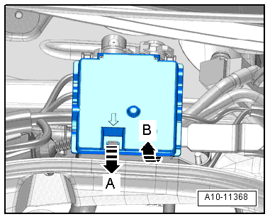
- Release the retainer in direction of -arrow A- and open the cover in direction of -arrow B-.
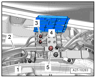
- Remove the connector -1- from the bracket and disconnect it.
- Remove the nuts -3, 4 and 5- and free up the wires and the wiring harness -2-.
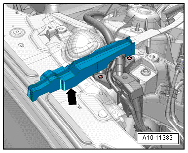
- Remove the foam wedge -1-.
- Remove the bolts -arrows-.
- Remove the Battery Jump Start Terminal -U6- and wiring harness upward.
Installing
Install in reverse order of removal. Note the following:
- Connect the battery. Required steps: vehicles without high voltage system.
Battery Jump Start Terminal -U6- Mount, Removing and Installing
Removing
- Remove the plenum chamber cover. Refer to → Body Exterior; Rep. Gr.50; Bulkhead; Plenum Chamber Cover, Removing and Installing.
- Remove the foam wedge -arrow- upward.
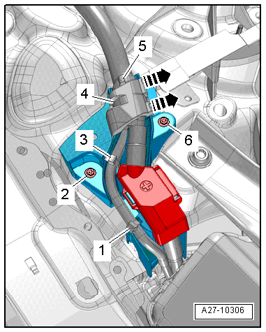
- Unlock and remove the cover -4- in direction of -arrows-.
- Cut the cable ties -1, 3 and 5-.
- Remove the bolts -2 and 6-.
- Unlock the cover -5- and move it to the side.
- Open the tabs -1 and 3- and remove the positive service terminal -2- from the bracket.
- Pull the mount -4- forward and swivel it out in direction of -arrow-.
Installing
Install in reverse order of removal. Note the following:
Note
When installing, install all cable ties at the same location.