Audi A6 Typ 4G: Adaptive Cruise Control
Overview - Adaptive Cruise Control (ACC)
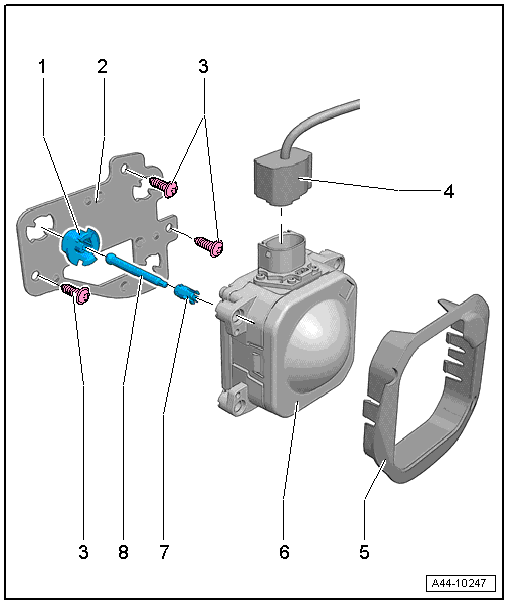
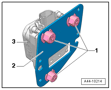
1 - Quick Release Fastener
- Quantity: 3
- Replace after removal
2 - Retaining Plate
- Removing and installing. Refer to → Chapter "Retaining Plate for Distance Regulation Control Module -J428-/Distance Regulation Control Module 2 -J850-, Removing and Installing".
3 - Screw
- 2.5 Nm
4 - Connector
- Check for damage, contact corrosion and water ingress, and service if necessary. Refer to → Electrical Equipment General Information; Rep. Gr.97; Wiring Harness and Connector Repairs.
5 - Cover
6 - Distance Regulation Control Module
- Right: Distance Regulation Control Module -J428-
- Left: Distance Regulation Control Module 2 -J850-
- Removing and installing. Refer to → Chapter "Distance Regulation Control Module -J428-/Distance Regulation Control Module 2 -J850-, Removing and Installing".
7 - Clip
- Must always be replaced if the stud bolt -item 8- was removed.
- Replacing. Refer to → Chapter "Clip on Distance Regulation Control Module -J428-/Distance Regulation Control Module 2 -J850-, Replacing".
8 - Stud Bolt
- Note the adjustment dimension.
Control Module for Adaptive Cruise Control, Removing and Installing
Distance Regulation Control Module -J428-/Distance Regulation Control Module 2 -J850-, Removing and Installing
 Note
Note
If replacing the control module, select the "Replace Control Module" function for the respective control module using the Vehicle Diagnostic Tester.
Removing
- Remove the air intake grille. Refer to → Body Exterior; Rep. Gr.63; Front Bumper; Overview - Bumper Cover.
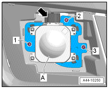
- Remove the screws -1, 2 and 3-.
Note
Clean and dry the area around the control module connector.
- Disconnect the connector -arrow-.
- Remove the distance regulation control module -A- from the bumper cover.
Installing
Install in the reverse order of removal. Note the following:
Note
Check the connector for damage, contact corrosion and water ingress, and service if necessary. Refer to → Electrical Equipment General Information; Rep. Gr.97; Wiring Harness and Connector Repairs.
- Calibrate the adaptive cruise control. Refer to → Chapter "Adaptive Cruise Control, Calibrating".
Retaining Plate for Distance Regulation Control Module -J428-/Distance Regulation Control Module 2 -J850-, Removing and Installing
Special tools and workshop equipment required
- Digital Caliper -VAS6335-
Removing
- Remove the distance regulation control module. Refer to → Chapter "Distance Regulation Control Module -J428-/Distance Regulation Control Module 2 -J850-, Removing and Installing".
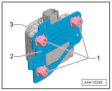
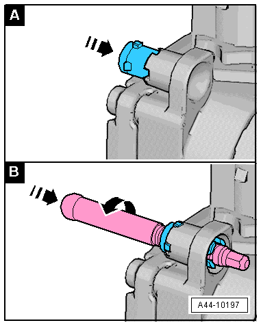
- Turn the quick release -1- counterclockwise.
- Remove the quick release from the stud bolts.
- Remove the retaining plate -2- from the distance regulation control module -3-.
Installing
Install in reverse order of removal. Note the following:
Note
- Replace the quick release.
- The stud bolts in the bracket are pre-set. If necessary, correct the setting.
- If the stud bolts were removed, then the clips on the distance regulation control module must be replaced. Refer to → Chapter "Clip on Distance Regulation Control Module -J428-/Distance Regulation Control Module 2 -J850-, Replacing".
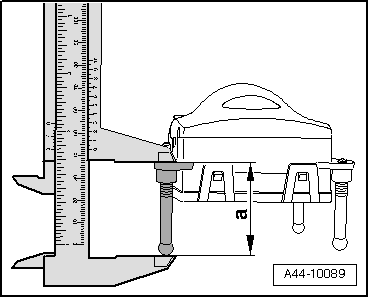
- Place the control module on a soft and clean surface.
- Measure the dimension -a- at all stud bolts using the Digital Caliper -VAS6335- and correct if necessary.
- The dimension -a- = 43.3 mm.
- Position the retaining plate -2- onto the distance regulation control module -item 3-.
- Carefully press the new quick release -4- onto the stud bolt -2-.
- Turn the quick release clockwise onto the retaining plate to the stop.
Clip on Distance Regulation Control Module -J428-/Distance Regulation Control Module 2 -J850-, Replacing
Note
- If the stud bolts were removed, then the clips on the distance regulation control module must be replaced.
- The clips cannot be removed without being damaged.
Procedure
- Remove the distance regulation control module retaining plate. Refer to → Chapter "Retaining Plate for Distance Regulation Control Module -J428-/Distance Regulation Control Module 2 -J850-, Removing and Installing".
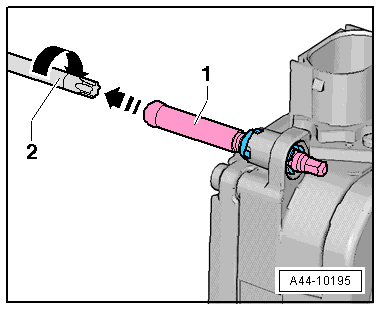
- Remove the stud bolt -1- using a suitable tool -2-.
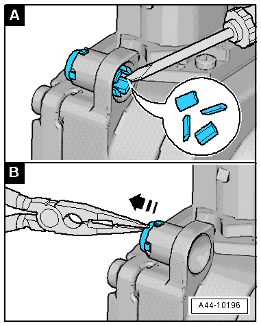
- Place a screwdriver between the hook and the housing.
- Bend every hook all the way around with the screwdriver until it audibly breaks off.
- To prevent the broken hook from getting caught on the housing, remove it from the inside of the clip using needle nose pliers.
- Insert the new clip into the hole in the housing from the left and then press on it by hand until it clicks into place.
- The tabs on the clip must sit correctly in the recesses.
- Install the stud bolt.
- The stud bolt must be parallel inside the hole and correctly aligned to the clip.
- Turn the stud bolt into the distance regulation control module up to the dimension -a-.
- Dimension -a- = 43.3 mm.
- Repeat this procedure on all the other clips, if necessary.
Adaptive Cruise Control, Calibrating
Before starting a calibration check if the vehicle is equipped with an infrared system. If this is the case depending on the damage claim the night vision system camera must be calibrated first.
Conditions
- The distance regulation control module must be calibrated during the following conditions:
- The Distance Regulation Control Module -J428-/Distance Regulation Control Module 2 -J850- was replaced.
- The Distance Regulation Control Module -J428-/Distance Regulation Control Module 2 -J850- was removed and installed.
- The front bumper was damaged.
- The front bumper was loosened, adjusted, or removed and installed.
- The rear axle toe was adjusted.
- The adjustment angle is greater than -0.8º to +0.8º.
- Too large of a vertical adjustment for the distance regulation control module (leads to a blind spot deactivation). Functional limitations emerge due to limited sensor sight, which is not the result of a dirty sensor or inclement weather conditions (for example, heavy rain/snowfall, iced over sensor, etc.).
- The DTC "no or incorrect basic setting/adaptation" is stored in the DTC memory.
Additional procedures. Refer to → Suspension, Wheels, Steering; Rep. Gr.44; Adaptive Cruise Control (ACC); Adaptive Cruise Control (ACC), Calibrating.
Special Tools
Special tools and workshop equipment required
- Digital Caliper -VAS6335-
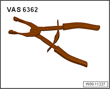
- Hose Clip Pliers -VAS6362-