Audi A6 Typ 4G: Clutch
Clutch
Overview - Flywheel and Dual Clutch
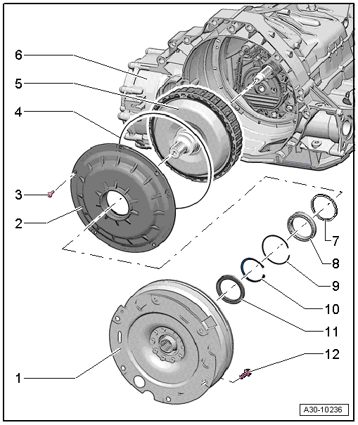
1 - Flywheel
- Refer to the Parts Catalog because there are different versions depending on the date of manufacture.
- Removing and installing. Refer to → Chapter "Flywheel, Removing and Installing".
2 - Clutch Cover
- There are different versions depending on the date of manufacture, with or without a thrust washer (-item 7-), allocation. Refer to the Parts Catalog.
- Removing. Refer to → Chapter "DSG Clutch, Removing".
- Installing. Refer to → Chapter "Dual Clutch, Installing".
3 - Bolt
- Tightening specification and sequence. Refer to → Fig. "Clutch Cover Tightening Specification and Sequence"
4 - O-Ring
- Replacing
5 - Dual Clutch
- Refer to the Parts Catalog because there are different versions depending on the date of manufacture.
- Removing. Refer to → Chapter "DSG Clutch, Removing".
- Installing. Refer to → Chapter "Dual Clutch, Installing".
- Perform the relevant "Guided Function" using the Vehicle Diagnostic Tester after replacing the dual clutch. Refer to → S tronic Transmission; Rep. Gr.39; Transmission Control.
6 - Transmission Housing
7 - Thrust Washer
- Depending on the date of manufacture, clutch cover allocation. Refer to the Parts Catalog.
8 - Ball Bearing
- For the dual clutch
- Replacing. Refer to → Chapter "Input Shaft Ball Bearing, Replacing".
9 - Locking Ring
- Replacing
- For ball bearing
10 - Locking Ring
- Replacing
- For the dual clutch
11 - Shaft Seal
- For the input shaft
- Replacing. Refer to → Chapter "Input Shaft Seal, Replacing".
12 - Bolt
- 60 Nm
- Replacing
Clutch Cover Tightening Specification and Sequence
- Tighten the bolts in three steps in the sequence shown:
.png)
Flywheel, Removing and Installing
Special tools and workshop equipment required
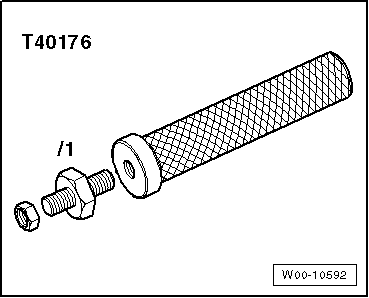
- Puller - Clutch Module -T40176-
- Clutch Disc Shaft Spline Lubricant -G 000 100-
- Grease. Refer to the Parts Catalog.
Removing
- Secure the transmission on the Engine And Transmission Holder -VAS6095-. Refer to → Chapter "Securing on Engine and Transmission Holder".
- Remove the left flange shaft. Refer to → Chapter "Left Flange Shaft, Removing and Installing".
- Attach the Puller - Clutch Module -T40176- to the flywheel -A- with the nut -B--arrow-.
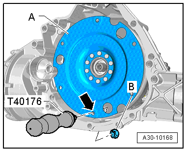
- Turn the Puller - Clutch Module -T40176- upward.
 Note
Note
To prevent the flywheel from tilting, counterhold it underneath as illustrated.
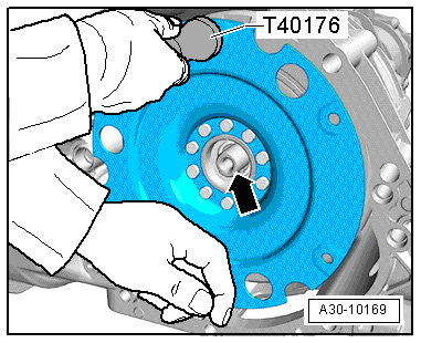
- Remove the flywheel from the input shaft -arrow-. Do not tilt the flywheel when doing this.
Installing
Install in reverse order of removal. Note the following:
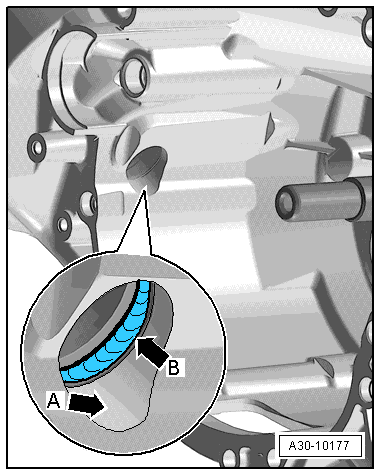
- Always clean the transmission housing in the area where the differential is accessed -arrow A- and the shaft seal -arrow B-.
 Note
Note
Replace the shaft seal between the differential and transmission housing -arrow B- if it is damaged. Refer to → Chapter "Left Seal, Replacing".
- Fill the space between the sealing- and dust lip half way with sealing grease. Refer to the Parts Catalog.
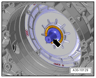
- Clean the input shaft -arrow-.
- Lubricate the input shaft splines using Grease for Clutch Disc Shaft Splines -G 000 100-.
- Slide the clutch module onto the input shaft -arrow- carefully without tilting it.

- Remove the Puller - Clutch Module -T40176- from the flywheel -A-.
- Install the left flange shaft. Refer to → Chapter "Left Flange Shaft, Removing and Installing".

DSG Clutch, Removing
Special tools and workshop equipment required
- Engine Support Bridge - Additional Hooks (2 pc.) -10-222A/2-
- Shop Crane -VAS6100-
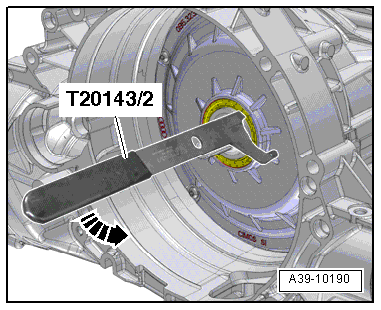
- Pulling Hook -T20143/2-
- Dual Clutch Lifting Device -T40123A-
- Oil Sump Assembly Pin -T40199-
Removing
- Secure the transmission on the Engine And Transmission Holder -VAS6095-. Refer to → Chapter "Securing on Engine and Transmission Holder".
- Remove the flywheel. Refer to → Chapter "Flywheel, Removing and Installing".
- Drain the ATF. Refer to → Chapter "ATF, Draining and Filling".
- Pry out the input shaft seal with the Pulling Hook -T20143/2-.
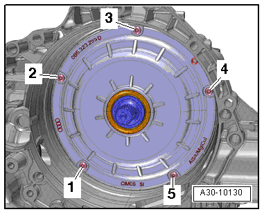
- Remove the bolts -1 through 5-.
- Turn the inside the Engine and Gearbox Jack -VAS6931- so that it is vertical.
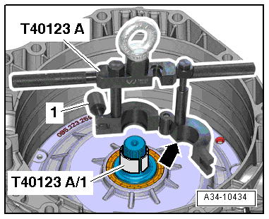
- Place the Dual Clutch Lifting Device Sleeve -T40123A/1- on the drive axle.
- Place the Dual Clutch Lifting Device -T40123A- on the drive axle.
- The edge -arrow- of the lifting device must grip under the Dual Clutch Lifting Device Sleeve -T40123A/1-.
- Close the lifting device and tighten the knurled nut -1- to approximately 20 Nm.
- Make sure the lifting device fits securely on the input shaft.
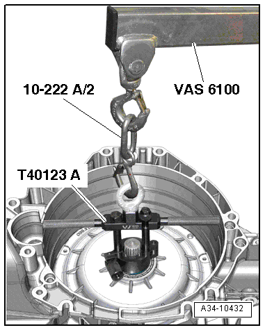
- Connect the Dual Clutch Lifting Device -T40123A- with the Engine Support Bridge - Additional Hooks (2 pc.) -10-222A/2- and engage in the Shop Crane -VAS6100-.
- Carefully remove the dual clutch out of the transmission housing.
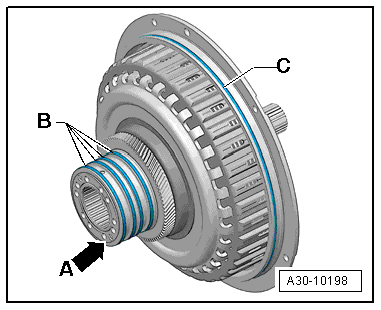
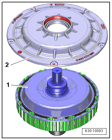
- Lay the dual clutch and cover on a soft surface so that the thin rib -arrow A- does not get damaged.
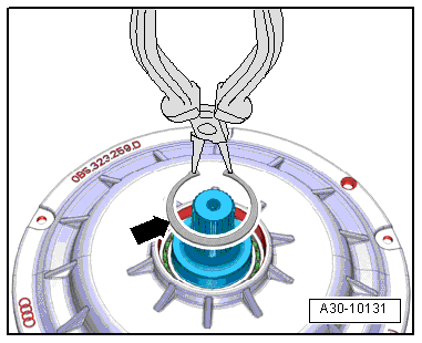
- Remove the locking ring -arrow- with locking ring pliers.
- Remove the clutch cover -2- from the dual clutch -1-.
 Note
Note
- If the clutch cover does not come off, gently strike the input shaft with a rubber hammer while a second technician lifts the clutch cover by hand.
- Be careful not to damage the thin rib -arrow A- when doing this.

Dual Clutch, Installing
Install in reverse order of removal. Note the following:
 Note
Note
Replace the O-ring and the circlip.
- Clean the sealing surface on the clutch cover.
- Turn the rectangular rings -B- on the hub and check for ease of movement and axial play.
 Note
Note
If the rectangular rings do not move easily, then the dual clutch must not be installed.
- Clean the transmission housing around the dual clutch and the sealing surface.
 Note
Note
Make sure no dirt can fall into the transmission while cleaning.
- Install the Oil Sump Assembly Pin -T40199- into the threaded hole in the transmission housing as illustrated.
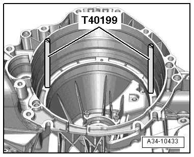
- Check the hole -arrow- in the transmission for wear grooves.
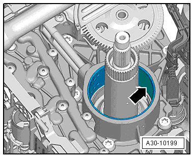
- Coat the O-ring -C- and hub -B- on the dual clutch with ATF.

- Install the dual clutch into the transmission housing. Using short lifting/turning motions, allow the input shaft to engage into the ATF pump splines and transmission shafts as illustrated.
- The dual clutch is installed correctly when the clutch cover O-ring noticeably contacts the edge of the transmission housing.

 Caution
- Do not let the O-ring get caught when installing.
- Always follow the tightening sequence when tightening the clutch cover bolts -1 through 5-. Refer to ( → Fig. "Clutch Cover Tightening Specification and Sequence").
- Tighten the clutch cover bolts -1 through 5- to the tightening specification and sequence. Refer to → Fig. "Clutch Cover Tightening Specification and Sequence".
- Replace the input shaft seal. Refer to → Chapter "Input Shaft Seal, Replacing".
- Install the flywheel. Refer to → Chapter "Flywheel, Removing and Installing".
- Fill with ATF after the transmission is installed:
- After installing the transmission, fill the ATF. Refer to → S tronic Transmission; Rep. Gr.34; Automatic Transmission Fluid; ATF, Draining and Filling.
- Perform the relevant "Guided Function" using the vehicle diagnostic tester after replacing the dual clutch. Refer to → S tronic Transmission; Rep. Gr.39; Transmission Control.

Special Tools
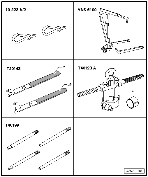
Special tools and workshop equipment required
- Engine Support Bridge - Additional Hooks (2 pc.) -10-222A/2-
- Shop Crane -VAS6100-
- Pulling hook -T20143/2-
- Dual Clutch Lifting Device -T40123A-
- Oil Sump Assembly Pin -T40199-
- Puller - Clutch Module -T40176-
- Clutch Disc Shaft Spline Lubricant -G 000 100-
