Audi A6 Typ 4G: Transmission, Transporting
Special tools and workshop equipment required
- Shop Crane -VAS6100-
- Hook And Support Tool -T40197-
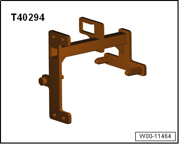
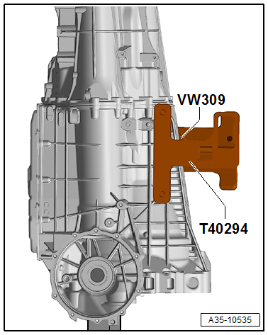
- Hook and Support Tool -T40294-
 DANGER!
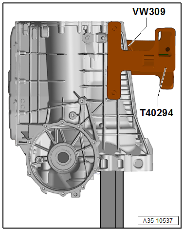
Do not use the Hook And Support Tool T40197 for the repair (Refer to → Chapter "Sensor Module , with integrated transmitters and sensors -G612-, -G632-, -G676 - and Circuit Board 3, Removing and Installing") - There is a risk of injury.
Only use the Hook and Support Tool T40294 for this operation.
Procedure
- The transmission is removed.
 Caution
Transmission components could be damaged if they are not set down correctly.
Do not set the transmission on the ATF pan.
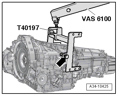
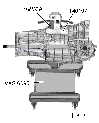
- Engage the Hook And Support Tool -T40197- in the holes on the right side of the transmission and secure it to the left side of the transmission with the knurled bolt -arrow-.
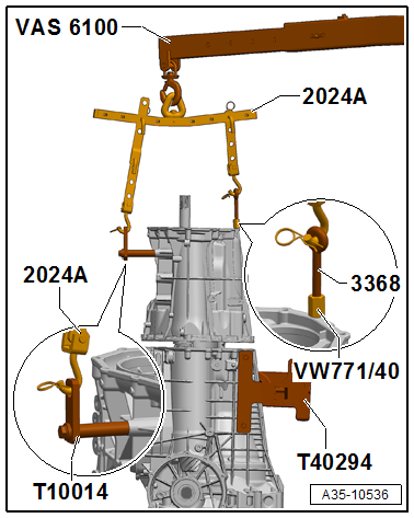
- Lift and transport the transmission with the Shop Crane -VAS6100-.
Transmission, Disassembling and Assembling
Overview - Transmission
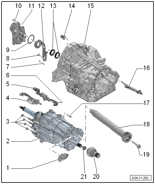
1 - Oil Guide
- For the input shaft
2 - Transmission Intermediate Housing
- With wheel set
3 - Gear Position Seal
- Only replace if damaged
- Removing and installing. Refer to → Fig. "Replace the Gear Position Seal".
4 - Front Oil Catch Tray
- Replace after removal
- Clipped onto the Sensor Module
5 - Sensor Module
- With integrated Transmission Input Speed Sensor 2 -G612-, Transmission Input Speed Sensor 1 -G632-, Drive Position Sensor -G676- and Circuit Board 3
- Refer to the Parts Catalog because there are different versions depending on the date of manufacture.
- Removing and installing. Refer to → Chapter "Sensor Module , with integrated transmitters and sensors -G612-, -G632-, -G676 - and Circuit Board 3 , Removing and Installing".
6 - Bolt
- 8 Nm
- Refer to the Parts Catalog because there are different versions depending on the date of manufacture.
7 - Bolt
- 4.5 Nm
8 - O-Ring
- Replacing
9 - O-Ring
- Replacing
10 - Bolt
- 25 Nm
- Quantity: 5
11 - Oil Pump
- Removing and installing. Refer to → Chapter "Oil Pump and Suction Jet Pump, Removing and Installing".
12 - Suction Jet Pump
- Replace the small O-ring (not shown in the illustration)
13 - Shaft Seal
- The Double seal is connected
- For the separating wall inside the transmission housing
- Replacing. Refer to → Chapter "Transmission Housing Separator Seals, Replacing".
14 - Connector Housing for the Sensor Module
- Removing and installing. Refer to → Chapter "Sensor Module , with integrated transmitters and sensors -G612-, -G632-, -G676 - and Circuit Board 3 , Removing and Installing".
15 - Transmission Housing
16 - Oil Guide
- To the front final drive
17 - Bolt
- Replacing
- Tightening specification and sequence. Refer to → Fig. "Transmission Intermediate Housing on the Transmission Housing - Tightening Specification and Sequence"
18 - Side Shaft
- With helical gear wheel
19 - Bolt
- 150 Nm +90º
- Replacing
- For the side shaft to the pinion
20 - Spur Gear
21 - Needle Bearing
Replace the Gear Position Seal
 Caution
There is a risk of damaging the gear position
Do not use any sharp-edged tools when removing the seals.
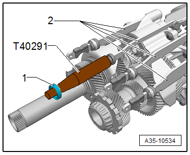
- Remove the seal by hand from the respective gear position -2-.
- Coat the new seal -1- with MTF and install on the Seal Installer - Gear Selector -T40291-.
- Place the Seal Installer - Gear Selector -T40291- on the respective gear position -2- and insert the seal -1-.
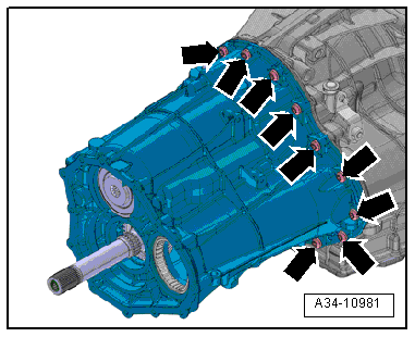
Transmission Intermediate Housing on the Transmission Housing - Tightening Specification and Sequence
 Note
Note
Replace the bolts.
- Tighten the bolts in two stages as described below:
.png)
Sensor Module , with integrated transmitters and sensors -G612-, -G632-, -G676 - and Circuit Board 3 , Removing and Installing
 DANGER!
Caution:
Do not use the Hook And Support Tool T40197 for the following described work procedures - There is a risk of injury.
Only use the Hook and Support Tool T40294 for this operation.
Special tools and workshop equipment required
- Hook and Support Tool -T40294-
- Counterhold - Side Shaft -T40217-
- Sensor Module Tool -T40228-
- Sealant. Refer to the Parts Catalog.
 Note
Note
- The Transmission Input Speed Sensor 2 -G612-, Transmission Input Speed Sensor 1 -G632-, Drive Position Sensor -G676- and Circuit Board 3 are integrated in the Sensor Module. The components can only be replaced as a single Sensor Module unit.
- Replace the wiring set for the sensor module (-item 39-) when replacing the Sensor Module.
Removing
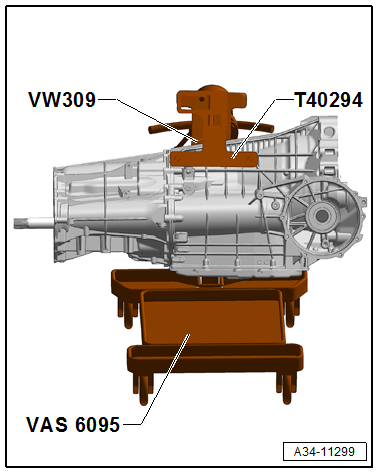
- Secure the transmission on the Engine And Transmission Holder -VAS6095-. Refer to → Chapter "Securing on Engine and Transmission Holder".
- Remove the flywheel. Refer to → Chapter "Flywheel, Removing and Installing".
- Remove the dual clutch. Refer to → Chapter "DSG Clutch, Removing".
- Remove the DSG Transmission Mechatronic -J743-. Refer to → Chapter "Mechatronic, Removing and Installing".
- Remove the oil pump and the suction jet pump. Refer to → Chapter "Oil Pump and Suction Jet Pump, Removing and Installing".
 Note
Note
The wiring set for the sensor module must be replaced when replacing the Sensor Module.
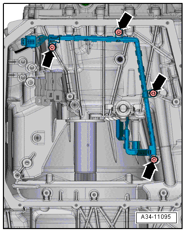
- Loosen the bolts -arrows- on the wiring set for the sensor module.
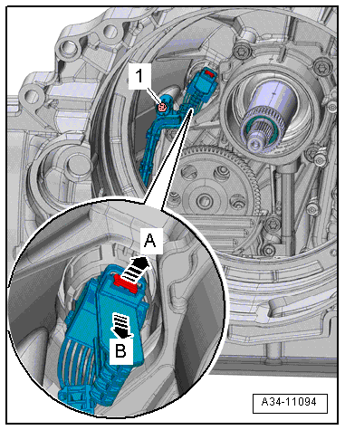
- Loosen the bolt -1-.
- Pull the fastener in direction of -arrow A- and remove the connector in direction of -arrow B- to disconnect the connector from the Sensor Module.
- Remove the wiring set for the sensor module.
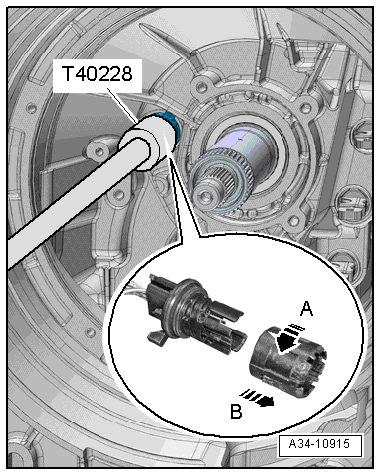
- Mount the Sensor Module Tool -T40228- on the connector housing, turn it all the way to the left in direction of -arrow A- and then remove the connector housing for the Sensor Module.
- Remove the connector housing for the Sensor Module in direction of -arrow B-.
- Remove the center differential housing and center differential. Refer to → Chapter "Center Differential Housing, Removing and Installing".
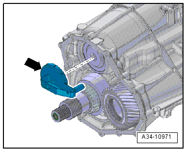
- Remove the oil guide for the input shaft -arrow-.
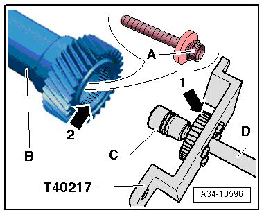
- Loosen the twelve-point bolt -A- for the side shaft -B- on the pinion as follows:
- Mount a twelve-point socket -C- (21 mm) with an extension -D- over the twelve-point bolt -A-.
- Insert the Counterhold - Side Shaft -T40217- with the outer splines -arrow 1- into the inner splines -arrow 2- on the side shaft.
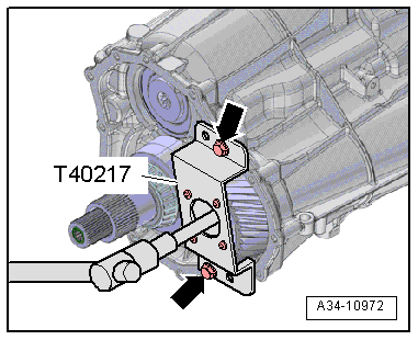
- Tighten the Counterhold - Side Shaft -T40217- on the transmission intermediate housing -arrows-.
 DANGER!
Do not use the Hook And Support Tool T40197 for the following described work procedure - There is a risk of injury.
Only use the Hook and Support Tool T40294 for this operation.
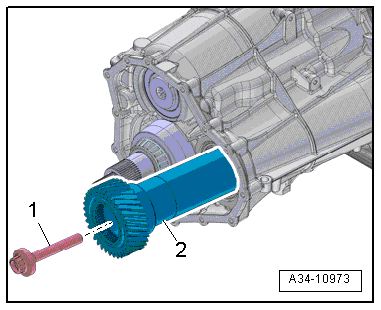
- Remove the bolt -1- and the side shaft -2-.
 Note
Note
The bolt has a high loosening torque.
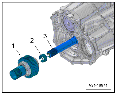
- Remove the spur gear -1- and needle bearing -2- from the output shaft -3-.
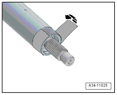
- Wrap the splines for the outer drive axle with adhesive tape in direction of -arrow-, so that the inner surfaces of the suction jet pump are not damaged when removing or installing.
- Coat the tape lightly with grease.
- Adjust the transmission housing on the engine/transmission holder so that it is vertical.
- The clutch side faces down.
- Remove the bolts -arrows- all around for the transmission intermediate housing.
- Install the Three Guide Pins - Gearbox -T40288- in a distance of approximately 120º in the transmission housing bolt holes.
 Note
Note
The Guide Pins - Gearbox -T40288- improve the removal of the transmission housing and prevent damage to the seals and components.

- Engage the transmission intermediate housing -1- with the wheel set on the Shop Crane -VAS6100- as shown in the illustration.
 WARNING
There is the risk of an accident if the support bridge parts are loose.
- Install each threaded connection on the Lifting Eyebolt -3368- and the Slide Hammer Set - Adapter 40 -VW771/40- until stop to make sure they are secure.
- Secure the hooks and locking pins on the Engine Sling -2024A- with cotter pins.
- Lift the transmission intermediate housing slowly and carefully off the transmission housing.
- Place the transmission intermediate housing on a workbench.
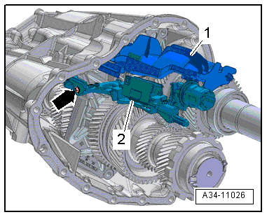
- Remove the bolt -arrow-, and then remove the Sensor Module-2-.
 Note
Note
The front oil catch tray -1- is engaged to the Sensor Module and will also be removed.
- Release the tabs to remove the front oil catch tray -1- from the Sensor Module.
Installing
- Tightening specifications. Refer to → Chapter "Overview - Transmission".
 Note
Note
- Replace any bolts that were tightened with an additional turn.
- There are different versions of the sensor module and screw, depending on the date of manufacture. Allocation. Refer to the Parts Catalog.
- Wrap the splines for the outer drive axle with adhesive tape in direction of -arrow-, so that the inner surfaces of the suction jet pump are not damaged when installing.
- Coat the tape lightly with grease.

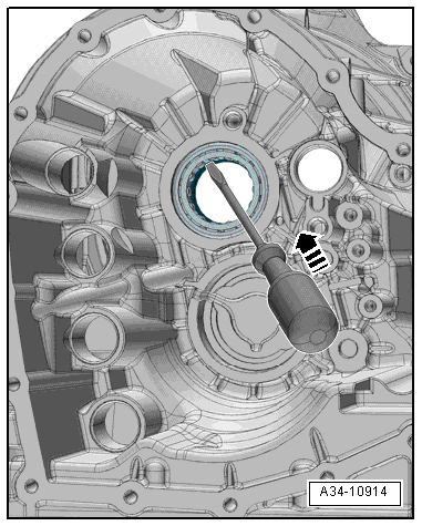
- Remove the shaft seal for the separator in the transmission housing starting from the transmission side with a screwdriver in direction of -arrow-.
 Note
Note
- Both of the shaft seals for the separator in the transmission housing must always be replaced.
- To prevent damaging the seals there are pushed in after assembling the transmission housing with the intermediate housing.
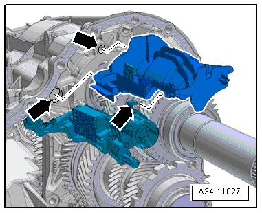
- Insert the Sensor Module into the guide openings and tighten it -arrow-.
- Replace the oil catch tray.
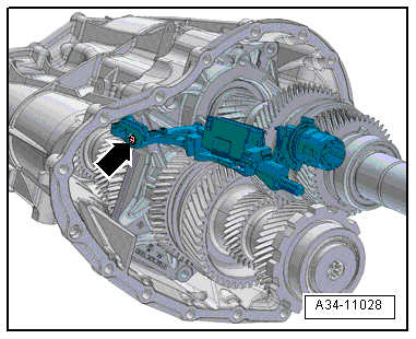
- Insert the front oil catch tray into the holes in the gear carrier and into the guide on the Sensor Module-arrows-.
- The oil catch tray must click into place.
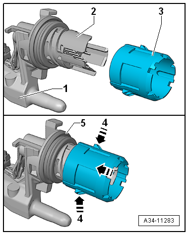
Prepare the connector for the Sensor Module for installation:
 Note
Note
It is necessary to replace the O-ring on the connector -2- for the Sensor Module if the Sensor Module is not being replaced.
- Check whether the connector -2- is secured on the bracket -1- for the Sensor Module.
- Push the connector housing -3- onto the connector until it clicks into place. Do not turn it.
- Coat the gear position seals with MTF -item 3-.
- Check if the retaining tabs in -4- can be pushed in.
- Check the oil catch tray seating.
- Check the seating of the sensor module seals -5-.
- Adjust the transmission housing on the engine/transmission holder so that it is vertical.
- Move the gearshift lever all the way in direction of travel in direction of -arrow-.
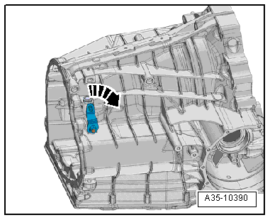
- Make sure the alignment sleeves -1 and 2- are installed inside the transmission housing.
 Note
Note
- The transmission housing sealing surface must be lightly roughened before the assembly.
- Pay attention while doing so that no debris get into the transmission housing.
- Suitable abrasive for example 3M bristle disk
- Coat the transmission housing flange -arrow- evenly and lightly with sealant. Refer to the Parts Catalog.
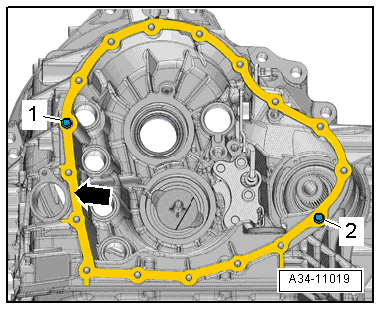
- Make sure the magnet -arrow- is installed inside the transmission housing.
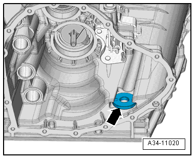
- Insert the front final drive oil guide into the transmission housing.
- The oil guide must be inserted into the holes in the transmission housing at three locations -arrows-.
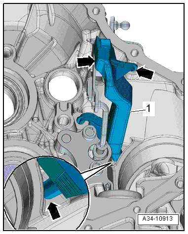
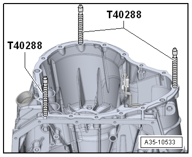
- Install the Guide Pins - Gearbox -T40288- in the threaded holes approximately 120º offset.
- Engage the transmission intermediate housing -1- with the wheel set on the Shop Crane -VAS6100- as shown in the illustration.
 WARNING
There is the risk of an accident if the support bridge parts are loose.
- Install each threaded connection on the Lifting Eyebolt -3368- and the Slide Hammer Set - Adapter 40 -VW771/40- until stop to make sure they are secure.
- Secure the hooks and locking pins on the Engine Sling -2024A- with cotter pins.

- Lower the transmission intermediate housing into the transmission housing slowly and carefully.
 Caution
There is a danger of damaging the Sensor Module.
When installing the transmission intermediate housing, pay close attention that the Sensor Module is not on the oil guide -1- and will not be damaged.
There is a risk of damaging the shift fork seal -item 3-.
When guiding the transmission intermediate housing pay special attention not to contact the shift fork seal.

- When lowering the transmission intermediate housing guide it so that the connector -1- from the Sensor Module is guided in the hole -arrow- on the transmission housing without tilting.
 Note
Note
The procedure from the transmission intermediate housing side is shown. The procedure from the transmission housing side must also be performed.
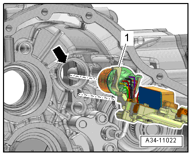
- Guild the transmission intermediate housing completely on the transmission housing and secure it. Refer to → Fig. "Transmission Intermediate Housing on the Transmission Housing - Tightening Specification and Sequence".
- Check if the connector retaining tabs for the sensor module are engaged in the transmission housing.

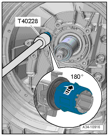
- Connect the Sensor Module Tool -T40228- flush with the connector housing for the Sensor Module.
 Note
Note
The tabs for the Sensor Module Tool -T40228- must securely mesh into the openings on the connector housing for the Sensor Module.
- Turn the connector housing with the Sensor Module Tool -T40228- 180º in the clockwise direction of -arrow- lock it into place.
- Install the shaft seal for the separator in the transmission housing. Refer to → Chapter "Transmission Housing Separator Seals, Replacing".
- Install the oil pump and the suction jet pump. Refer to → Chapter "Oil Pump and Suction Jet Pump, Removing and Installing".
 Note
Note
- The wiring set for the sensor module must be replaced when replacing the Sensor Module.
- Bolt tightening specification: position -item 38-.
- Tighten the bolts -arrows- on the wiring set for the sensor module.

- Carefully press the connector on the Sensor Module completely opposite the direction of -arrow B-.
- Secure the fastener opposite the direction of -arrow A-.
- Make sure that the connector is secured and fastened correctly on the Sensor Module.
- Tighten the bolt -1-.
 Note
Note
Bolt tightening specification: position -item 38-.

- Mount the needle bearing -2- and spur gear -1- on the output shaft -3-.

- Insert the side shaft -2- with the bolt -1- into the transmission intermediate housing.

- Insert the side shaft -B- all the way onto the pinion and into the transmission cover.
Tighten the twelve-point bolt -A- for the side shaft -B- on the pinion as follows:
- Mount a twelve-point socket -C- (21 mm) with an extension -D- over the twelve-point bolt -A-.
- Insert the Counterhold - Side Shaft -T40217- with the outer splines -arrow 1- into the inner splines -arrow 2- on the side shaft.

- Tighten the Counterhold - Side Shaft -T40217- on the transmission intermediate housing -arrows-.
- Tighten the bolt for the side shaft.

- Mount the oil guide for the input shaft -arrow-.
Installation is performed in reverse order of removal.
- Install the center differential housing and the center differential. Refer to → Chapter "Center Differential Housing, Removing and Installing".
- Install the DSG Transmission Mechatronic -J743-. Refer to → Chapter "Mechatronic, Removing and Installing".
- Push the separator shaft seal in the transmission housing. Refer to → Chapter "Transmission Housing Separator Seals, Replacing".
- Install the dual clutch. Refer to → Chapter "Dual Clutch, Installing".
- Install the flywheel. Refer to → Chapter "Flywheel, Removing and Installing".

Oil Pump and Suction Jet Pump, Removing and Installing
Special tools and workshop equipment required
- Counterhold - Side Shaft -T40217-
- Sensor Module Tool -T40228-
- Sealant. Refer to the Parts Catalog.
Removing
- Secure the transmission on the Engine And Transmission Holder -VAS6095-. Refer to → Chapter "Securing on Engine and Transmission Holder".
- Remove the flywheel. Refer to → Chapter "Flywheel, Removing and Installing".
- Remove the dual clutch. Refer to → Chapter "DSG Clutch, Removing".
- Remove the DSG Transmission Mechatronic -J743-. Refer to → Chapter "Mechatronic, Removing and Installing".
- Wrap the splines for the outer drive axle with adhesive tape in direction of -arrow-, so that the inner surfaces of the suction jet pump are not damaged when removing or installing.
- Coat the tape lightly with grease.

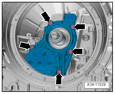
- Remove the bolts -arrows- and push the oil pump forward on the input shaft.
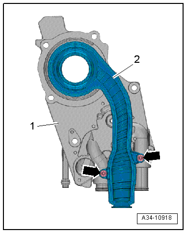
- Remove the bolts -arrows- for the suction jet pump -2- on the back of the oil pump -1-.
 Note
Note
The oil pump is shown removed.
- Remove the oil pump and suction jet pump separately from the input shaft.
Installing
- Tightening specifications. Refer to → Chapter "Overview - Transmission".
 Note
Note
- Replace any bolts that were tightened with an additional turn.
- Replace the O-rings.
- Wrap the splines for the outer drive axle with adhesive tape in direction of -arrow-, so that the inner surfaces of the suction jet pump are not damaged when installing.
- Coat the tape lightly with grease.

- Push the O-ring -2- onto the seal seat on the suction jet pump -1-.
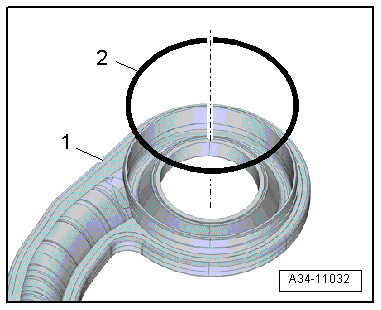
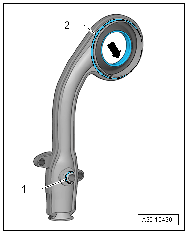
- Check the sealing surface -arrow- on the inside of the large opening in the suction jet pump for damage and replace if necessary.
- Check that the small O-rings -1- are in the correct places on the suction jet pump.
- Push the suction jet pump -2- and oil pump -1- separately onto the input shaft.
 Note
Note
The oil pump is shown removed.
- Position the suction jet pump on the oil pump and tighten the bolts -arrows-.

- Tighten the oil pump -arrows-.

Installation is performed in reverse order of removal.
- Remove the adhesive tape.
- Install the DSG Transmission Mechatronic -J743-. Refer to → Chapter "Mechatronic, Removing and Installing".
- Install the dual clutch. Refer to → Chapter "Dual Clutch, Installing".
- Install the flywheel. Refer to → Chapter "Flywheel, Removing and Installing".

Transmission Housing Separator Seals, Replacing
Special tools and workshop equipment required
- Seal Installer - Clutch Housing -T40260-
Procedure
- Secure the transmission on the Engine And Transmission Holder -VAS6095-. Refer to → Chapter "Securing on Engine and Transmission Holder".
- Remove the flywheel. Refer to → Chapter "Flywheel, Removing and Installing".
- Remove the dual clutch. Refer to → Chapter "DSG Clutch, Removing".
- Remove the DSG Transmission Mechatronic -J743-. Refer to → Chapter "Mechatronic, Removing and Installing".
- Remove the oil pump and the suction jet pump. Refer to → Chapter "Oil Pump and Suction Jet Pump, Removing and Installing".
 Caution
Danger of causing damage to the transmission.
In the following procedures, the input shaft surface must not come in contact with hard objects. Damage to the sealing surface on the input shaft will result in leaks.
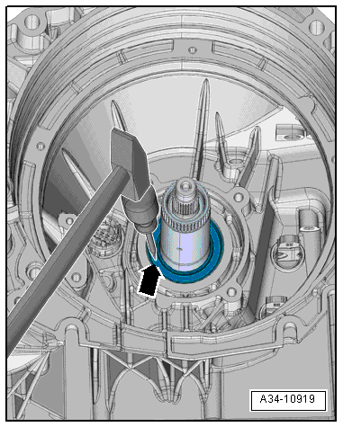
- Place a punch on the shaft seal and drive in a small hole -arrow-.
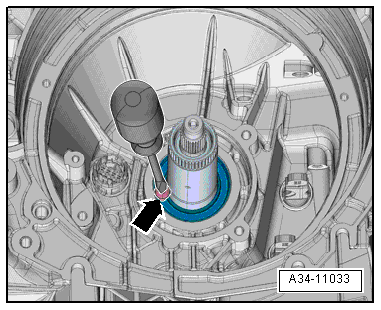
- Install a screw -arrow- with a large head into the hole in the shaft seal.
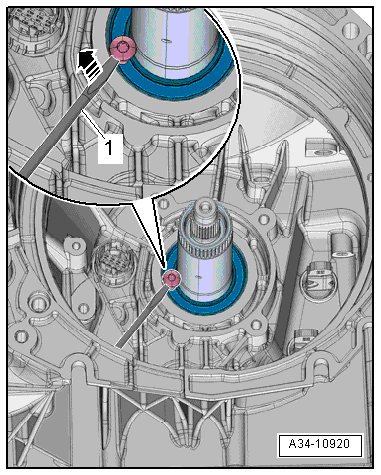
- Remove the outer shaft seal using a wide screwdriver in direction of -arrow-.
- Remove the inner shaft seal the same way.
 Caution
There is the danger of causing damage to the roller bearing behind the inner shaft seal.
Do not hit the punch too hard when making the hole in the inner shaft seal otherwise the bearing cage for the roller bearing behind it will get damaged.
 Note
Note
Remove both shaft seals from the transmission side using a screwdriver in direction of -arrow- with the transmission disassembled.

- Position the new shaft seals for installation.
 Note
Note
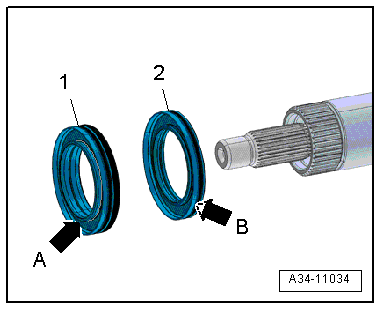
The shaft seals -1- and -2- are supplied as one part, and must be coated with MTF before installing.
- The spiral spring -arrow A- on the outer shaft seal -1- must face the dual clutch.
- The spiral spring -arrow B- on the inner shaft seal -2- must face the transmission.
- Clip the shaft seals together and install them.
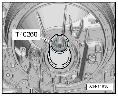
- Install the shaft seals flush from the clutch side using the Seal Installer - Clutch Housing -T40260-.
 Note
Note
The Seal Installer - Clutch Housing -T40260- can be extended using the Press Piece - 60mm -VW415A-.
Installation is performed in reverse order of removal.
- Install the oil pump. Refer to → Chapter "Oil Pump and Suction Jet Pump, Removing and Installing".
- Install the DSG Transmission Mechatronic -J743-. Refer to → Chapter "Mechatronic, Removing and Installing".
- Install the dual clutch. Refer to → Chapter "Dual Clutch, Installing".
- Install the flywheel. Refer to → Chapter "Flywheel, Removing and Installing".
