Audi A6 Typ 4G: Mechatronic
Overview - Mechatronic
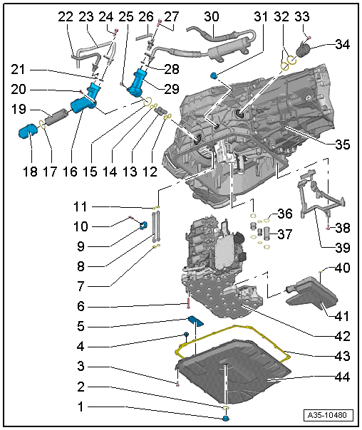
1 - ATF Drain Plug
- Tightening specification -item 1-
2 - Seal
- Replacing
3 - Bolt
- Tightening specification and sequence. Refer to → Fig. "ATF Oil Pan, Tightening Specification and Sequence"
- Replacing
4 - Expanding Rivet
- For attaching the gasket to the ATF oil pan
- Not required for installation
5 - Magnet
- Quantity: 2
- Insert into the depression in the ATF oil pan
- Make sure the entire surface contacts oil pan
6 - Bolt
- Replacing
- Tightening specification and sequence. Refer to → Fig. " Mechatronic, Tightening Specification and Sequence"
7 - O-Rings
- Replacing
8 - ATF Pressure Pipes (Coupling Pressure)
- Depending on the date of manufacture, versions may be different. The ATF pressure pipe (clutch pressure) in transmissions of the new version are a single unit and made out of plastic.
- Plastic ATF pressure pipes are backward compatible.
- Replacing
9 - Retaining Plate
- Only for the ATF pressure pipe (clutch pressure) made out of metal
10 - Bolt
- 10 Nm
- Only for the ATF pressure pipe (clutch pressure) made out of metal
11 - O-Rings
- Replacing
12 - O-Rings
- Replacing
13 - ATF Pipes
- Different versions, depending on date of manufacture
14 - O-Rings
- Replacing
15 - O-Ring
- Replacing
- Different versions, depending on date of manufacture
16 - ATF Filter Housing
- For transmissions with a replaceable ATF filter
- Different versions, depending on date of manufacture
17 - O-Ring
- For transmissions with a replaceable ATF filter
- Replacing
18 - ATF Filter Cover
- 8 Nm
- For transmissions with a replaceable ATF filter
- Note that there are different versions
19 - ATF Filter
- Replace each time the ATF is changed and after performing a repair on the transmission
- Pay attention to the allocation. Refer to the Parts Catalog is also called a filter
20 - Bolt
- 10 Nm
- Quantity: 3
- For transmissions with a replaceable ATF filter
21 - O-Rings
- Replacing
- For transmissions with a replaceable ATF filter
22 - ATF Return Pipe
- For transmissions with a replaceable ATF filter
- Removing and installing. Refer to → S tronic Transmission; Rep. Gr.34; ATF Circuit; ATF Pipes, Removing and Installing
23 - ATF Supply Pipe
- For transmissions with a replaceable ATF filter
- Removing and installing. Refer to → S tronic Transmission; Rep. Gr.34; ATF Circuit; ATF Pipes, Removing and Installing
24 - Bolt
- Tightening specification. Refer to → S tronic Transmission; Rep. Gr.34; ATF Circuit; Overview - ATF Circuit
- For transmissions with a replaceable ATF filter
25 - Bolt
- 10 Nm
- Quantity: 3
- For transmissions with an ATF pipe filter
26 - ATF Return Pipe
- For transmissions with an ATF pipe filter
- Removing and installing. Refer to → S tronic Transmission; Rep. Gr.34; ATF Circuit; ATF Pipes, Removing and Installing
27 - Bolt
- Tightening specification. Refer to → S tronic Transmission; Rep. Gr.34; ATF Circuit; Overview - ATF Circuit
- For transmissions with an ATF pipe filter
28 - O-Rings
- Replacing
- For transmissions with an ATF pipe filter
29 - ATF Pipe Connection
- For transmissions with an ATF pipe filter
30 - ATF Pipe Filter
- Replace the ATF pipe filter whenever replacing the transmission or repairing the transmission
- Removing and installing. Refer to → S tronic Transmission; Rep. Gr.34; ATF Circuit; ATF Filter, Removing and Installing
31 - ATF Fill and Check Plug
- Tightening specification -item 4-
32 - O-Rings
- Replacing
33 - Bolt
- 8 Nm
34 - Connector Housing
- To remove, remove the bolt -33- and turn the connector housing counter-clockwise.
35 - Transmission Housing
36 - O-Rings
- Replacing
37 - ATF Pipes
- Depending on the date of manufacture, versions may be different. The ATF pipes in transmissions for the new version are a single unit and made out of plastic.
- Plastic ATF pressure pipes are backward compatible.
- Replacing
38 - Bolt
- 8 Nm
- Quantity: 5
39 - Wiring Set for the Sensor Module
- Removing and installing. Refer to → Chapter "Sensor Module , with integrated transmitters and sensors -G612-, -G632-, -G676 - and Circuit Board 3 , Removing and Installing".
- Replace if the Sensor Module is replaced.
40 - O-Ring
- Replacing
41 - ATF Suction Filter
- Removing and installing. Refer to → Chapter "ATF Filter, Removing and Installing".
42 - DSG Transmission Mechatronic -J743-
- Removing and installing. Refer to → Chapter "Mechatronic, Removing and Installing".
- Tightening specification and sequence → Fig. " Mechatronic, Tightening Specification and Sequence".
- Perform the relevant "Guided Function" using the vehicle diagnostic tester after replacing the DSG Transmission Mechatronic -J743-. Refer to → S tronic Transmission; Rep. Gr.39; Transmission Control.
- Remove the circuit board from the DSG Transmission Mechatronic -J743-. Refer to → Chapter "Overview - Mechatronic Circuit Boards".
43 - Seal
- Replacing
- Installing
44 - ATF Pan
- Removing and installing. Refer to → Chapter "Oil Pan, Removing and Installing".
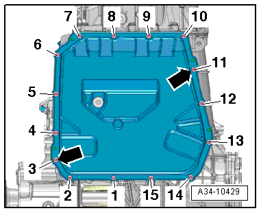
ATF Oil Pan, Tightening Specification and Sequence
- Tighten the bolts in two stages as described below.
1. Install the bolts -arrows- hand-tight.
2. Tighten the screws -1 through 15- diagonally to 10 Nm and in steps.
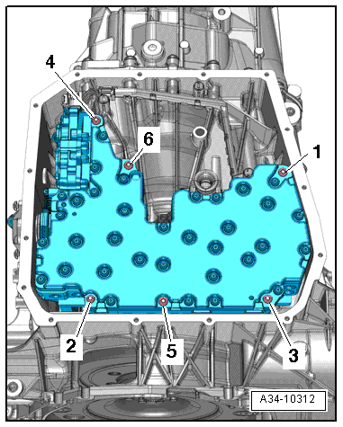
Mechatronic, Tightening Specification and Sequence
- Tighten the bolts to 10 Nm in the sequence -1 to 6-.
Oil Pan, Removing and Installing
Removing
 Note
Note
- General Repair Instructions. Refer to → Chapter "Repair Information".
- Rules for cleanliness when working on the DSG transmission. Refer to → Chapter "Guidelines for Clean Working Conditions".
The Transmission is Installed.
It is also possible to remove and install the ATF pan when the transmission is installed. Depending on the vehicle model and the engine version, additional work may be required to be able to reach the ATF pan. Refer to → S tronic Transmission; Rep. Gr.34; Mechatronic
Transmission Removed.
- The transmission is secured to the engine/transmission holder. Refer to → Chapter "Securing on Engine and Transmission Holder".
- Place the Used Oil Collection and Extraction Unit -SMN372500- under the transmission.
- Drain the ATF. Refer to → Chapter "ATF, Draining and Filling".
- Diagonally Loosen the screws -1 through 15-.
- Remove the bolts and the ATF pan.
 Note
Note
Ignore -arrows-.

Installing
Install in reverse order of removal. Note the following:
- Clean the sealing surfaces.
- Replace the ATF oil pan bolts and gasket.
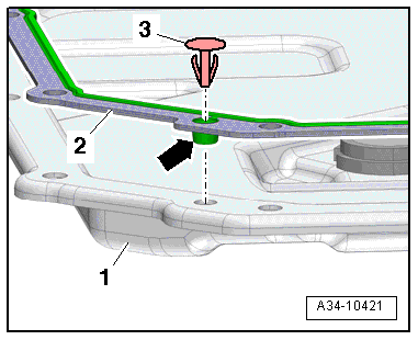
- Insert the guides -arrow- on the new gasket -2- into the ATF fluid pan -1-.
- Attach the gasket (if equipped) and expanding rivets -3- to the ATF pan.
 Note
Note
Clips item -3- are only used for assembly help during production.
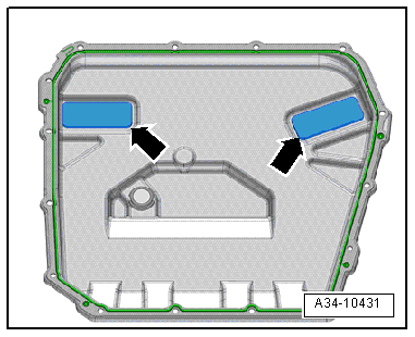
- Clean the magnets -arrows- in the ATF pan.
- Make sure the magnets completely contact the depressions in the ATF oil pan.
- Tighten the ATF oil pan screws. Refer to → Fig. "ATF Oil Pan, Tightening Specification and Sequence".
- After installing the ATF pan, fill with ATF. Refer to → S tronic Transmission; Rep. Gr.34; Automatic Transmission Fluid; ATF, Draining and Filling

ATF Filter, Removing and Installing
Special tools and workshop equipment required
- Used Oil Collection and Extraction Unit -SMN372500-
Removing
 Note
Note
- General Repair Instructions. Refer to → Chapter "Repair Information".
- Rules for cleanliness when working on the DSG transmission. Refer to → Chapter "Guidelines for Clean Working Conditions".
- Place the Used Oil Collection and Extraction Unit -SMN372500- under the transmission.
- Remove the ATF oil pan. Refer to → Chapter "Oil Pan, Removing and Installing".
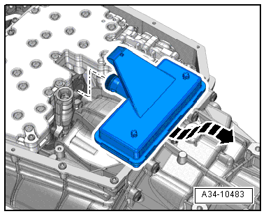
- Carefully pull the ATF suction filter to the rear and off the Mechatronic in direction of -arrow-.
Installing
Install in reverse order of removal. Note the following:
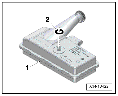
- Install the O-ring -2- on the rear support on the ATF suction filter -1-.
- Install the ATF suction filter suction collar all the way into the opening in the transmission fluid pump.
- The support with the O-ring must fit into the hole inside the transmission housing.
- Install the ATF pan. Refer to → Chapter "Oil Pan, Removing and Installing".
- After installing the transmission, fill with ATF. Refer to → S tronic Transmission; Rep. Gr.34; Automatic Transmission Fluid; ATF, Draining and Filling
Mechatronic, Removing and Installing
Special tools and workshop equipment required
- Used Oil Collection and Extraction Unit -SMN372500-
Removing
 Note
Note
- General repair instructions. Refer to → Chapter "Repair Information".
- Rules for cleanliness when working on the DSG transmission. Refer to → Chapter "Guidelines for Clean Working Conditions".
 Caution
There is a risk of destroying the transmission control module (Mechatronic) with static discharge.
- Always "discharge" the static electricity before working with electric connectors. Do this by touching a grounded object, for example vehicle ground, the vehicle or the hoist.
- Do not touch contacts in transmission connector with hands.
The Transmission is Installed.
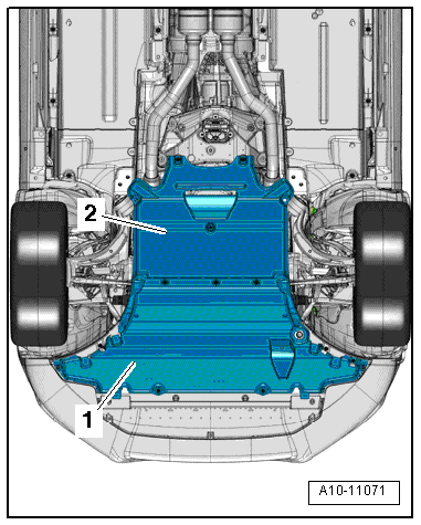
- Remove the noise insulations -1 and 2-. Refer to → Body Exterior; Rep. Gr.66; Noise Insulation; Noise Insulation, Removing and Installing.
 Caution
Danger of Causing Damage to the Transmission.
Do not start the engine if there is no ATF in the transmission or if the DSG Transmission Mechatronic -J743- is removed.
- Move the selector lever into "P".
- Turn off the ignition and remove the key.

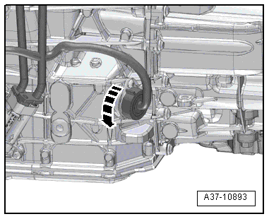
- Turn the twist lock counter-clockwise in direction of -arrow- and disconnect the connector from the transmission.
Transmission, Removed or Installed
- Remove the ATF oil pan. Refer to → Chapter "Oil Pan, Removing and Installing".
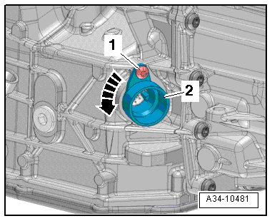
- Remove the bolt -1-.
- Turn the connector housing -2- counter-clockwise in direction of -arrow- and remove it.
Vehicles with an ATF Pipe Filter
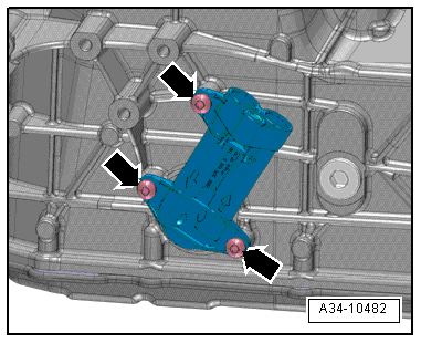
- Remove the bolts -arrows- and remove the connecting piece for the ATF pipes. Refer to → S tronic Transmission; Rep. Gr.34; ATF Circuit.
Vehicles with ATF Filter
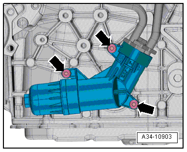
- Remove the bolts -arrows- and remove the ATF filter housing. Refer to → S tronic Transmission; Rep. Gr.34; ATF Circuit
All Vehicles
 Note
Note
- The ATF pipes -2- cannot remain attached to the mechatronic, because these would otherwise block the removal.
- Always replace the seals -3 and 4-.
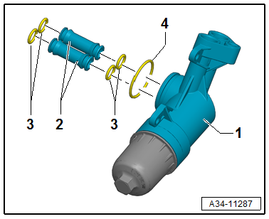
- Carefully pull the ATF filter to the rear and off the Mechatronic in direction of -arrow-.
 Caution
There is a risk of destroying the transmission control module (Mechatronic) with static discharge.
- Always "discharge" the static electricity before working with electric connectors. Do this by touching a grounded object, for example vehicle ground, the vehicle or the hoist.
- Do not touch contacts in transmission connector with hands.

- Pull the retainer in direction of -arrow 1-, push the release down in direction of -arrow 2- and disconnect the connector.
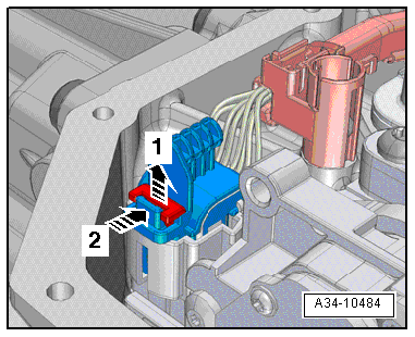
- Remove the bolts in reverse order: -6 to 1-.
 Caution
Risk of causing Damage to the Mechatronic.
- Only bolts -6 to 1- may be loosened.
- If other bolts are loosened, this may affect the function of the Mechatronic unit or it may come apart.
 Note
Note
- The sealing surface must not be damaged.
- The Mechatronic fits partially inside the transmission.
- If the Mechatronic must be removed, then a second technician will be needed to keep it from falling. Another alternative, the bolts -1 and 2- can be installed slightly to hold the Mechatronic in place while it is being removed.
- Remove the Mechatronic.
 Caution
Danger of Damaging the Sensor on the Back Side of the Mechatronic.
Lay the Mechatronic with the bolt head side facing down only.

Installing
 Note
Note
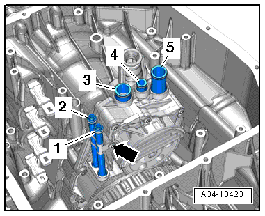
- The ATF pressure pipes -1 through 5- are made out of plastic on the newer version of the transmission.
- The bracket for the ATF pressure pipes -1 and 2- is not present in this case.
- The metal ATF pressure pipes can be replaced with plastic ATF pressure pipes. To do so, remove the bolt -arrow- and remove the bracket.
- Coat the seals with ATF before installing.
- If equipped, remove the bolt for the ATF pressure pipe bracket -arrow-.
- Replace the ATF pressure pipes (clutch pressure) -1 and 2-.
- Replace the ATF pipes -3 through 5-.
- If equipped, tighten the bolt without the ATF pressure pipe bracket -arrow-.
- Tightening specifications. Refer to → Chapter "Overview - Mechatronic".
 Note
Note
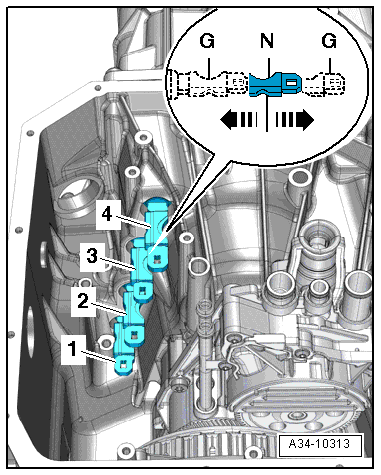
Make sure all shift forks and gear positions are in the center position before installing the DSG transmission Mechatronic -J743-.
Adjust the Shift Forks
- First check the shift positions for the shift forks -1 through 4- by hand.
Each shift fork has three positions:
- -G- is engaged
- Idle -N- (center position)
- -G- is engaged
- Move all four shift forks one time into each position -arrows- one after the other.
- After doing this, move the shift forks back into the center position -N-.
Adjust the Gear Selector:
 Caution
There is a risk of destroying the transmission control module (Mechatronic) with static discharge.
- Always "discharge" the static electricity before working with electric connectors. Do this by touching a grounded object, for example vehicle ground, the vehicle or the hoist.
- Do not touch contacts in transmission connector with hands.
- Do not pry out the plunger on the sensors.
The gear shifter must be adjusted differently depending on the date of manufacture of the Mechatronic.
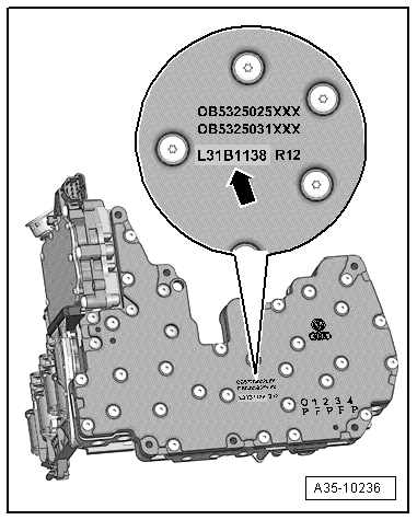
The date of manufacture is located only on the Mechatronic identification -arrow-.
The Mechatronic identification consists of:
.png)
The gear positions must be adjusted to a different adjustment value from Mechatronic "L31B1138".
 Note
Note
- A Mechatronic with the identification. "L31A1140" was built before Mechatronic "L31B1138" because it was built by the 1st shift (A1) on a Monday.
- A Mechatronic with the identification "L31C1009" was built after Mechatronic "L31B1138" because it was built by the 3rd shift (C1) on Monday.
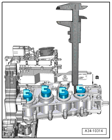
- Move the gear position back and forth and set the 4 gear positions on the back of the Mechatronic in the center position to dimension -a-.
For Mechatronic with Identification Through "L31B1137":
- Dimension -a- = 28 mm
For Mechatronic with Identification From "L31B1137":
- Dimension -a- = 32 mm.
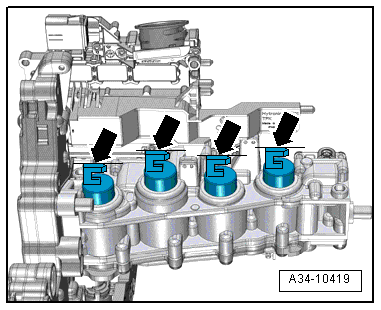
- Align the gear selector yokes -arrows- so that they engage into the eyes in the shift fork when being installed.
- Insert the Mechatronic into the transmission housing.
- The Mechatronic and its bolts must fit easily into the holes in the transmission.
- If the Mechatronic does not go in easily, then it is possible that a shift fork or a gear selector is not in its center position. Check the center position and adjust if necessary.

After installing the Mechatronic:
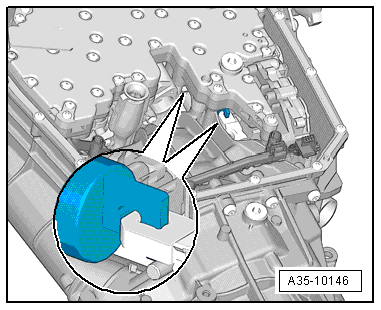
- Using a flashlight, check all the gear selectors through the opening between the Mechatronic and the transmission housing.
- All four gear selector yokes must fit correctly in the shift fork eyes.
- Tighten the Mechatronic bolts. Refer to → Fig. " Mechatronic, Tightening Specification and Sequence".
Install in reverse order, paying attention to the following:
 Caution
There is a risk of destroying the transmission control module (Mechatronic) with static discharge.
- Always "discharge" the static electricity before working with electric connectors. Do this by touching a grounded object, for example vehicle ground, the vehicle or the hoist.
- Do not touch contacts in transmission connector with hands.
- Make sure the connector is correctly connected to the Mechatronic.
- Install the ATF suction filter. Refer to → Chapter "ATF Filter, Removing and Installing".
- Install the ATF pan. Refer to → Chapter "Oil Pan, Removing and Installing".
- Install the ATF filter housing or ATF line connecting pieces (depending on the version). Refer to → S tronic Transmission; Rep. Gr.34; ATF Circuit
 Caution
Danger of leaks!
- Always replace the seals on the oil lines and the filter housing and coat with ATF.
- Ensure a clean sealing surface.
Transmission Removed
- Install the transmission. Refer to → S tronic Transmission; Rep. Gr.34; Transmission, Removing and Installing; Transmission, Installing.
The Transmission Is Installed
- Fill with ATF. Refer to → S tronic Transmission; Rep. Gr.34; Automatic Transmission Fluid; ATF, Draining and Filling.
- Perform the relevant "Guided Function" using the vehicle diagnostic tester after replacing the DSG Transmission Mechatronic -J743-. Refer to → S tronic Transmission; Rep. Gr.39; Transmission Control.

Overview - Mechatronic Circuit Boards
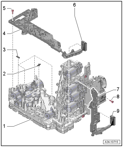
1 - DSG Transmission Mechatronic -J743-
- Removing and installing. Refer to → Chapter "Mechatronic, Removing and Installing".
- Perform "Guided Functions" using the Vehicle Diagnostic Tester after replacing the DSG Transmission Mechatronic -J743-. Refer to → S tronic Transmission; Rep. Gr.39; Transmission Control
2 - Protector
- Cross-shaped
- Quantity: 2
- For Sub-Transmission 1 Valve 3 -N435- and Sub-Transmission 2 Valve 3 -N439-
- Install also in a transmission that does not have a protector
3 - Protector
- Rectangular
- Quantity: 4
- For the Sub-Transmission 1 Valve 4 -N436-, Sub-Transmission 2 Valve 4 -N440-, Cooling Oil Valve -N471-, Main Pressure Valve -N472-
- Install also in a transmission that does not have a protector
4 - Circuit Board 1
- Removing and installing. Refer to → Chapter "Mechatronic Circuit Board, Removing and Installing".
- The contact springs on the circuit board can be connected one time only. A circuit board cannot be used again once it has been removed.
5 - Bolt
- Tightening specification and sequence. Refer to → Fig. "Circuit board 1 - Tightening Specification and Sequence"
6 - Connector
- Use a 3.5 mm screwdriver to unlock the connector.
7 - Circuit Board 2
- Removing and installing. Refer to → Chapter "Mechatronic Circuit Board, Removing and Installing".
- The contact springs on the circuit board can be connected one time only. A circuit board cannot be used again once it has been removed.
8 - Bolt
- Tightening specification and sequence. Refer to → Fig. "Circuit board 2 - Tightening Specification and Sequence"
9 - Connector
- Use a 3.5 mm screwdriver to unlock the connector.
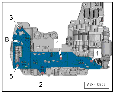
Circuit board 1 - Tightening Specification and Sequence
- Tighten the bolts to 3 Nm in the following sequence: -1 to 5-.
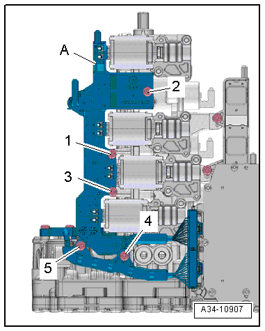
Circuit board 2 - Tightening Specification and Sequence
- Tighten the bolts to 3 Nm in the following sequence: -1 to 5-.
Mechatronic Circuit Board, Removing and Installing
Removing
- Remove the DSG Transmission Mechatronic -J743-. Refer to → Chapter "Mechatronic, Removing and Installing".
- Place the Mechatronic on a clean, soft surface.
 Caution
There is a risk of destroying the transmission control module (Mechatronic) with electrostatic discharge.
Always "discharge" the static electricity before working with electric connectors. Do this by touching a grounded object, for example vehicle ground, the vehicle or the hoist.
 Caution
Using an inappropriate tool can damage the transmission control module (Mechatronic).
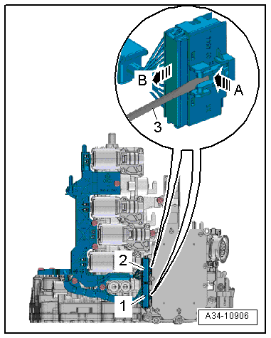
- The Mechatronic must be replaced if the locking mechanism for the connectors gets damaged while unlocking and disconnecting the connectors.
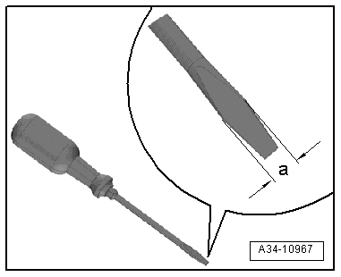
- Use a screwdriver -a- = maximum 3.5 mm to unlock the connector.
- Unlock the connectors -1 and 2- on the Mechatronic carefully using a screwdriver -3- in direction of -arrow A- and disconnect them in direction of -arrow B-.
- Loosen the screws -1, 2 and 3- on the small circuit board -A- approximately 5 mm.
- Remove the screws -4 and 5- completely and move the wiring guide to the side.
 Caution
There is a danger of an insufficient contact connection.
The contact springs on the circuit board can be connected one time only. A circuit board cannot be used again once it has been removed.

- Pull circuit board 2 just far enough until the contact springs -2- on the circuit board are free from the contacts -1- on the valves.
- Remove the screws -1, 2 and 3- carefully and remove circuit board 2.
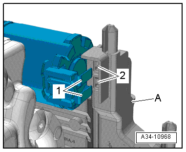
- Loosen the screws -1 through 5- on the large circuit board -B- approximately 5 mm.
 Caution
There is a danger of an insufficient contact connection.
The contact springs on the circuit board can be connected one time only. A circuit board cannot be used again once it has been removed.

- Pull circuit board 1 just far enough until the contact springs -2- on the circuit board are free from the contacts -1- on the valves.
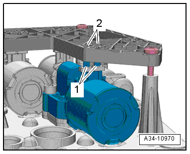
- Remove the screws -1 through 5- completely and remove circuit board 1.

Installing
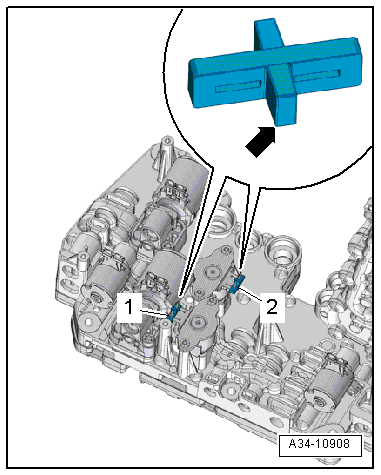
- Install a cross-shaped protector -arrow- on the valve contacts:
1 - Sub-Transmission 1 Valve 3 -N435-
2 - Sub-Transmission 2 Valve 3 -N439-
 Note
Note
Install a protector in the transmission if the transmission did not have one installed before.
- Install a rectangular protector -arrow- on the contacts on the remaining valves:
1 - Sub-Transmission 2 Valve 4 -N440-
2 - Main Pressure Valve -N472-
3 - Sub-Transmission 1 Valve 4 -N436-
4 - Cooling Oil Valve -N471-
 Note
Note
Install a protector in the transmission if the transmission did not have one installed before.
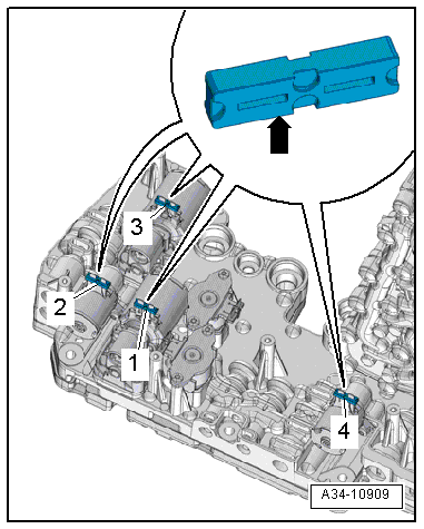
- Position the new circuit board 1 -B- carefully on the Mechatronic.
- Install the screws -1 to 5- approximately 2 turns as a guide.
- Push circuit board 1 carefully onto the contacts.
- Install the screws -1 to 5- all way hand-tight and then tighten them to the tightening specification.

- Position the new circuit board 2 -A- carefully on the Mechatronic.
- Install the screws -1, 2 and 3- approximately 2 turns as a guide.
- Push circuit board 2 carefully onto the contacts.
- Position the wiring guide on the alignment sleeves on the small circuit board.
- Install the screws -1 to 5- all way hand-tight and then tighten them to the tightening specification.
- Connect the connectors so that they click into place.
- Install the DSG Transmission Mechatronic -J743-. Refer to → Chapter "Mechatronic, Removing and Installing".

ATF Filter, Removing and Installing
Special tools and workshop equipment required
- Used Oil Collection and Extraction Unit -SMN372500-
 Note
Note
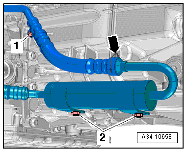
- There are two different ATF filter versions depending on the engine and the date of manufacture.
- Replace the ATF line filter -arrow- only when replacing a transmission. Removing and installing. Refer to → S tronic Transmission; Rep. Gr.34; ATF Circuit.
 Note
Note
The ATF filter -A- must be changed each time the ATF is changed.
Removing the ATF Filter
 Note
Note
- Refer to → Chapter "Guidelines for Clean Working Conditions".
- Always clean the ATF lines and ATF cooler with compressed air (maximum 10 bar (145 psi) ) and then flush with ATF before installing a replacement transmission.
- Drain the ATF. Refer to → Chapter "ATF, Draining and Filling".
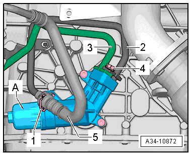
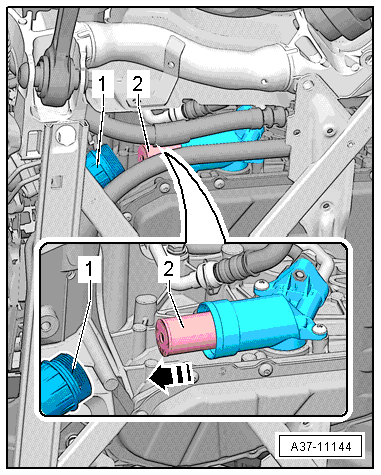
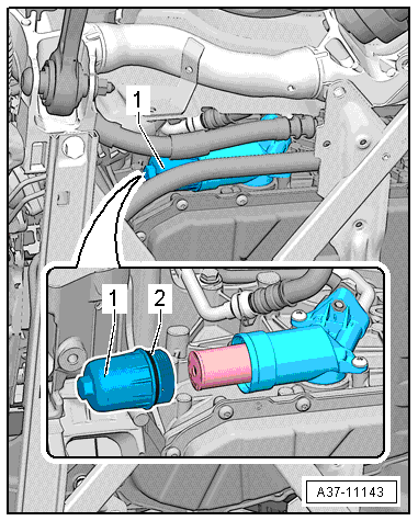
- If equipped loosen the securing strap -3- and remove the anti-twist mechanism -1-.
- Remove the cover for the ATF filter -1- and drain the ATF.
- Remove the ATF filter -2- in direction of -arrow- and remove from below.
Installing
 Caution
Danger of leaks!
- Always replace the seals on the oil lines and the filter housing and coat with ATF.
- Ensure a clean sealing surface.
Install in reverse order of removal. At the same time pay attention to the following:
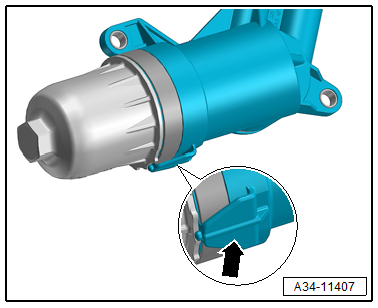
There are two different versions of ATF filter housing.
If the factory installed anti-twist mechanism -arrow- is not present, install an ATF-filter cover with upgradable anti-twist mechanism.
 Note
Note
The retrofittable anti-twist mechanism and the related ATF filter cover are available from 07/2014. Refer to the Parts Catalog.
 Caution
Leaking ATF filter.
Only use the assigned respective ATF-filter cover for the respective ATF filter housing/
Allocation of the ATF-Filter Cover to the ATF Filter Housing
 Note
Note
Position of the part number for the ATF filter housing.
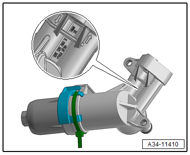
.png)
 Note
Note
- Replace the O-ring on the ATF filter cover.
- Replace the ATF filter.
 Caution
Danger of causing damage to the transmission.
The new ATF filter must not come in contact with water. Even the smallest amount of water, such as a drip of water from the engine compartment or moisture from hands will cause the surface of the ATF filter to swell up. Small paper particles from the filter can come loose and contaminate the Mechatronic.
- Coat the O-ring -2- on the new ATF filter -1- with ATF before installing.
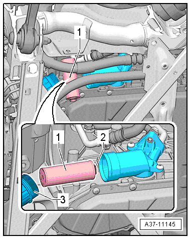
- Coat the O-ring -2- on the ATF filter cover -1- with ATF.
- Install the ATF filter cover -1- and tighten to tightening specifications.
Vehicles without A Factory Installed Anti-Twist Mechanism:
 Caution
Filter housing leak.
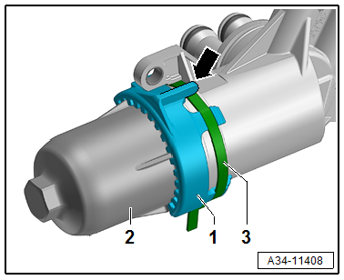
On filter housing without a factory installed anti-twist mechanism the filter cover must always be replaced with upgradable anti-twist mechanism -1-.
- Secure the anti-twist mechanism -1- on the ATF-filter cover -2- with the securing strap -3-.
 Note
Note
The anti-twist mechanism retaining tab -arrow- must touch the filter housing as shown.
- Clean the transmission and attachments.
Tightening Specification. Refer to → Chapter "Overview - Mechatronic".
- Fill with ATF. Refer to → S tronic Transmission; Rep. Gr.34; Automatic Transmission Fluid; ATF, Draining and Filling.


