Audi A6 Typ 4G: Component Location Overview - Telephone System
Telephone System, through MY 2014
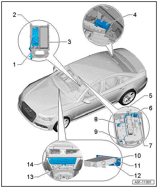
1 - Telephone Baseplate -R126-
- Removing and installing. Refer to → Chapter "Front Telephone Baseplate -R126-, Removing and Installing, through MY 2014".
2 - Bolt
- 1 Nm
- Quantity: 5
3 - Center Console Storage Compartment
- Removing and installing. Refer to → Body Interior; Rep. Gr.68; Center Console; Front Center Console Storage Compartment, Removing and Installing.
4 - Cellular Telephone Amplifier -R86-
- Connector assignment. Refer to → Chapter "Cellular Telephone Amplifier -R86- Connector Assignment, through MY 2014".
- Removing and installing. Refer to → Chapter "Cellular Telephone Amplifier -R86-, Removing and Installing, through MY 2014".
5 - Front Interior Lamp -W1-
- Microphone Unit in Front Roof Module -R164-
- Overview. Refer to → Chapter "Overview - Microphone Unit".
6 - 6-Pin Connector -T6e-
7 - Left Front Microphone -R140-
- Removing and installing. Refer to → Chapter "Microphone Unit in Front Roof Module -R164-, Removing and Installing".
8 - Right Front Microphone -R141-
- Removing and installing. Refer to → Chapter "Microphone Unit in Front Roof Module -R164-, Removing and Installing".
9 - Interior Microphone -R74-
- Removing and installing. Refer to → Chapter "Microphone Unit in Front Roof Module -R164-, Removing and Installing".
10 - Information Electronics Control Module 1 -J794-
- Cell phone preparation connector assignment, RMC. Refer to → Chapter "Cell Phone Preparation Connector Assignment, RMC and 9ZF"
- Pin assignment, cell phone preparation MMI. Refer to → Chapter "Cell Phone Preparation Connector Assignment, MMI, 9ZF".
- Bluetooth car telephone, connector assignment. Refer to → Chapter "Bluetooth Car Phone Connector Assignment, MMI, 9ZW".
- Bluetooth hands-free calling connector assignment, RMC. Refer to → Chapter "Bluetooth Hands-Free Calling Connector Assignment, RMC 9ZX".
- Bluetooth hands-free calling connector assignment, MMI. Refer to → Chapter "Bluetooth Hands-Free Setup Connector Assignment, MMI, 9ZX".
- Removing and installing. Refer to → Chapter "Information Electronics Control Module 1 -J794-, Removing and Installing".
11 - Trim
12 - Bolt
- 1 Nm
- Quantity: 4
13 - Bolt
- 3 Nm
14 - Information Electronics Control Module 1 -J794-
Telephone System, from MY 2015
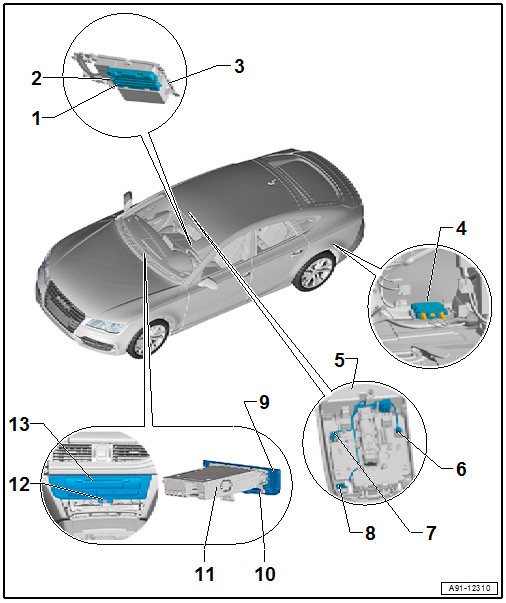
1 - Telephone Baseplate -R126-
- Connector assignment. Refer to → Chapter "Telephone Baseplate -R126- Connector Assignment, from MY 2015".
- Removing and installing. Refer to → Chapter "Front Telephone Baseplate -R126-, Removing and Installing, from MY 2015".
2 - Bolt
- 1 Nm
3 - Storage Compartment in Center Armrest
- Removing and installing. Refer to → Body Interior; Rep. Gr.68; Center Console; Front Center Console Storage Compartment, Removing and Installing.
4 - Cellular Telephone Amplifier -R86-
- Connector assignment. Refer to → Chapter "Cellular Telephone Amplifier -R86- Connector Assignment, from MY 2015".
- Removing and installing. Refer to → Chapter "Cellular Telephone Amplifier -R86-, Removing and Installing, from MY 2015".
5 - Front Interior Lamp -W1-
- Microphone Unit in Front Roof Module -R164-
- Overview. Refer to → Chapter "Overview - Microphone Unit".
6 - Left Front Microphone -R140-
- Removing and installing. Refer to → Chapter "Microphone Unit in Front Roof Module -R164-, Removing and Installing".
7 - Right Front Microphone -R141-
- Removing and installing. Refer to → Chapter "Microphone Unit in Front Roof Module -R164-, Removing and Installing".
8 - Interior Microphone -R74-
- Removing and installing. Refer to → Chapter "Microphone Unit in Front Roof Module -R164-, Removing and Installing".
9 - Trim
10 - Bolt
- 1 Nm
- Quantity: 4
11 - Information Electronics Control Module 1 -J794-
- Connector assignment. Refer to → Wiring diagrams, Troubleshooting & Component locations.
- Phone boc connector assignment. Refer to → Chapter "Audi Phone Box Connector Assignment, 9ZE, from MY 2015".
- Removing and installing. Refer to → Chapter "Information Electronics Control Module 1 -J794-, Removing and Installing".
12 - Bolt
- 3 Nm
13 - Information Electronics Control Module 1 -J794-
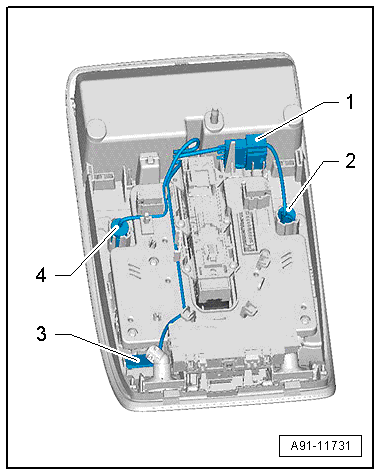
Overview - Microphone Unit
One microphone (Interior Microphone -R74-) is connected directly to the Digital Sound System Control Module -J525-. The other microphones are connected to the Information Electronics Control Module 1 -J794-.
Microphone Unit in Front Roof Module -R164-
1 - 6-Pin Connector -T6e-
2 - Microphone (blue) to Information Electronics Control Module 1 -J794-
3 - Microphone (black) to Digital Sound System Control Module -J525-
4 - Microphone (gray) to Information Electronics Control Module 1 -J794-
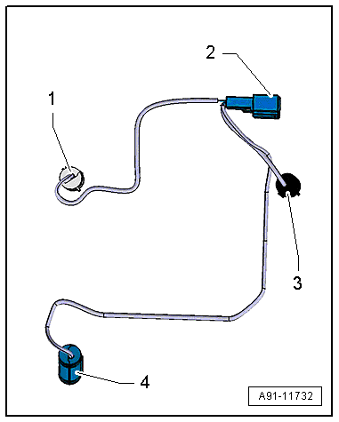
Connector assignment
1 - Left Front Microphone -R140-, gray
2 - 6-Pin Connector -T6e-, Pin 1-2: Left Front Microphone -R140- (gray), Pin 3-4: Interior Microphone -R74- (black), Pin 5-6: Right Front Microphone -R141- (blue)
3 - Right Front Microphone -R141-, blue
4 - Interior Microphone -R74-, black
Microphone Unit in Front Roof Module -R164-, removing and installing. Refer to → Chapter "Microphone Unit in Front Roof Module -R164-, Removing and Installing".