Audi A6 Typ 4G: Connector Assignments
Front Information Display Control Head -J685- Connector Assignment
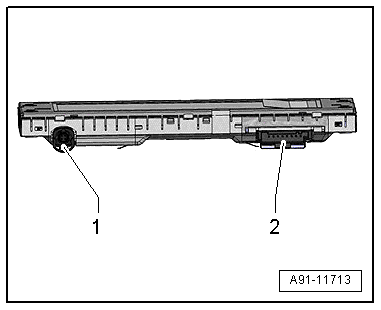
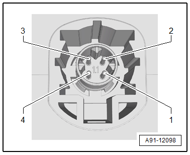
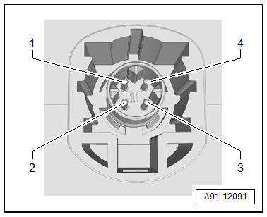
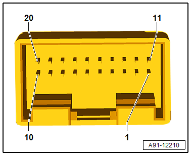
Front Information Display Control Head -J685-
1 - 4-Pin Connector -T4dd-/4-Pin Connector -T4de- from the Information Electronics Control Module 1 -J794-
2 - 8-Pin Connector -T8ag-
 Note
Note
Unlisted connector terminals are not assigned.
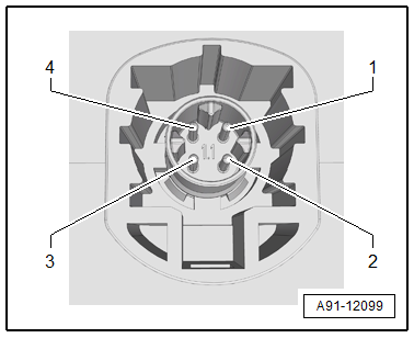
1 - 4-Pin Connector -T4dd-/4-Pin Connector -T4de-
All pins are connected to the Information Electronics Control Module 1 -J794-.
Through MY 2014
1 - Ground
2 - LVDS (+)
3 - LIN
4 - LVDS (-)
From MY 2015
1 - Ground
2 - LVDS (+)
3 - Ground
4 - LVDS (-)
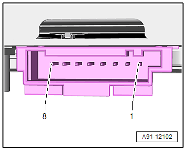
2 - 8-Pin Connector -T8ag-
1 - Not Assigned
2 - Not Assigned
3 - Not Assigned
4 - Terminal 30
5 - Terminal 31
6 - Not Assigned
7 - CAN bus high to Information Electronics Control Module 1 -J794-, from MY 2015 and 7UG
8 - CAN bus low to Information Electronics Control Module 1 -J794-, from MY 2015 and 7UG
Multimedia Display Unit 1/2 -Y22-/-Y23-, Connector Assignment
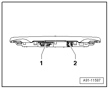
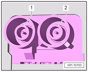
Multimedia Display Unit 1 -Y22-
1 - 8-Pin Connector -T8ao-
2 - 4-Pin Connector -T4en-
Note
Unlisted connector terminals are not assigned.
1 - 8-Pin Connector -T8ao-
1 - Not Assigned
2 - Not Assigned
3 - Terminal 31
4 - Terminal 30
5 - Terminal 31
2 - 4-Pin Connector -T4en-
All pins are connected to the Information Electronics Control Module 2 -J829-.
1 - Ground
2 - LVDS (+)
3 - LIN
4 - LVDS (-)
Multimedia Display Unit 2 -Y23-
1 - 8-Pin Connector -T8ap-
2 - 4-Pin Connector -T4eo-
Note
Unlisted connector terminals are not assigned.
1 - 8-Pin Connector -T8ap-
1 - Not Assigned
2 - Not Assigned
3 - Terminal 31
4 - Terminal 30
5 - Terminal 31
2 - 4-Pin Connector -T4eo-
All pins are connected to the Information Electronics Control Module 2 -J829-.
1 - Ground
2 - LVDS (+)
3 - LIN
4 - LVDS (-)
MMI Navigation Connector Assignment, 7T2
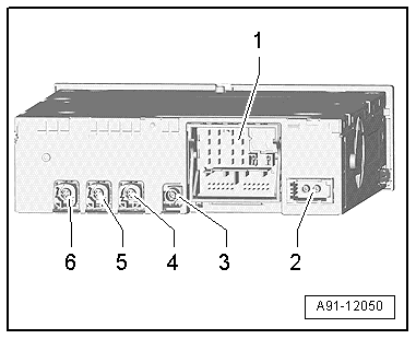
Information Electronics Control Module 1 -J794-
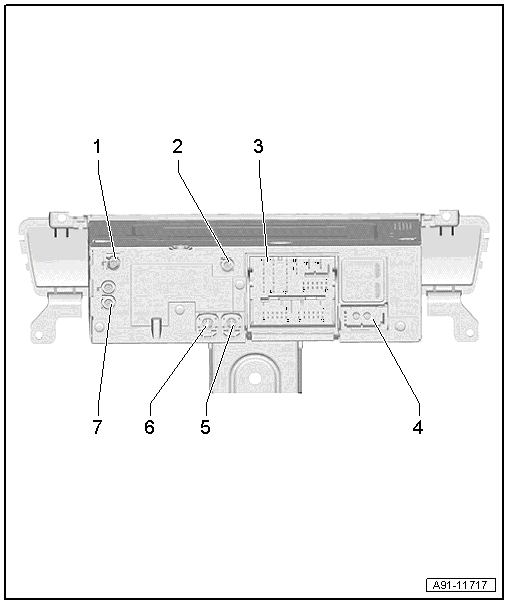
1 - DAB Connection from Antenna Amplifier 3 -R112-, Digital Radio Antenna -R183-, only ER1/ER2 and QV3
- SAT connection from Roof Antenna -R216-, Satellite Antenna -R170-, only ER3 and QV8
2 - GPS Connection from the Roof Antenna -R216-
3 - Connection Block with Four Multi-Pin Connectors
4 - MOST Bus
5 - 4-Pin Connector -T4z- to the External Audio Source Connection -R199-
6 - 4-Pin Connector -T4df- to the Front Information Display Control Head -J685-
7 - AM/FM/FM2 Antenna Connection
Note
Unlisted connector terminals are not assigned.
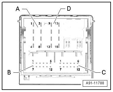
3 - Connection block with four multi-pin connectors
A - 8-Pin Connector -T8e-
1 - Right rear speaker (+)
2 - Right front speaker (+)
3 - Left front speaker (+)
4 - Left rear speaker (+)
5 - Right rear speaker (-)
6 - Right front speaker (-)
7 - Left front speaker (-)
8 - Left rear speaker (-)
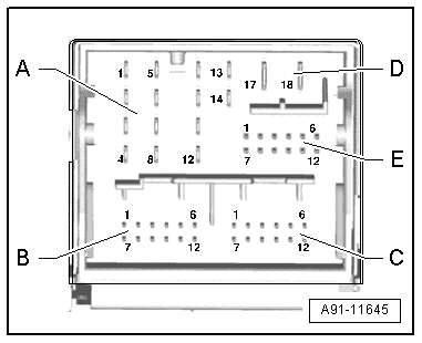
B - 12-Pin Connector -T12c-
1 - Data from Multimedia System Control Head -E380-
2 - Res BT Multimedia System Control Head -E380-
3 - Not Assigned
4 - Microphone input (+) from Microphone Unit in Front Roof Module -R164-, Left Front Microphone -R140-
5 - CVBS cable (-) for the Rearview Camera System Control Module -J772-
6 - DIAG signal from Telephone Baseplate -R126-
7 - Data to the Multimedia System Control Head -E380-
8 - Wake UP Multimedia System Control Head -E380-
9 - Res HU to the Multimedia System Control Head -E380-
10 - Not Assigned
11 - CVBS cable (+) for the Rearview Camera System Control Module -J772-
12 - Microphone input (-) for the Microphone Unit in Front Roof Module -R164-, Left Front Microphone -R140-
C - 12-Pin Connector -T12e-
All pins are connected to the External Audio Source Connection -R199-.
1 - LF-In ground
2 - Right LF-In
3 - USB, +5 V
4 - USB, ground
5 - iPod, ACC Power
6 - Detect
7 - Left LF-In
8 - LF-In ground shielding
9 - CVBS cable (+)
10 - CVBS cable (-)
11 - iPod data
12 - iPod data
D - 8-Pin Connector -T8f-
9 - Subwoofer -R211-
10 - Center Speaker -R208-
13 - Subwoofer -R211-
14 - Center Speaker -R208-
17 - Terminal 31
18 - Terminal 30
E - 12-Pin Connector -T12d-
7 - Ring-break Diagnostic Cable
12 - Switch-on signal to Telephone Baseplate -R126-/Cellular Telephone Amplifier -R86-
4 - MOST Bus
1 - Output
2 - Input
5 - 4-Pin Connector -T4z-
All pins are connected to the External Audio Source Connection -R199-.
1 - D (+)
2 - iPod recognized
3 - D (-)
4 - Ground
6 - 4-Pin Connector -T4df-
All pins are connected to the Front Information Display Control Head -J685-.
1 - LVDS (-)
2 - LIN
3 - LVDS (+)
4 - Ground
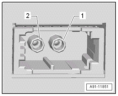
7 - AM/FM1/FM2 antenna connection
1 - Chamber 2, AM/FM1 from Antenna Amplifier 2 -R111-, Radio Antenna 2 -R93-
2 - Chamber 1, FM2 from Antenna Amplifier -R24-, Antenna -R11-
Information Electronics Control Module 2 -J829- Connector Assignment
Information Electronics Control Module 2 -J829-
1 - Connection block with four multi-pin connectors
2 - MOST Bus
3 - CVBS input from the DVD Changer -R161-
4 - 4-Pin Connector -T4eh- to the Multimedia Display Unit 1 -Y22-, left
5 - 4-Pin Connector -T4ek- to the External Audio Source Connection 2 -R231-
6 - 4-Pin Connector -T4ei- to the Multimedia Display Unit 2 -Y23-, right
Note
Unlisted connector terminals are not assigned.
1 - Connection block with four multi-pin connectors
A - 8-Pin Connector -T8l-
3 - Wake UP to the Multimedia Control Head 2 -E499-
6 - Res MU to Multimedia Control Head 2 -E499-
7 - Ring-break Diagnostic Cable
B - 12-Pin Connector -T12ad-
5 - FBAS wire (-) from the TV Tuner -R78- (Not available for North America)
11 - FBAS wire (+) from the TV Tuner -R78- (Not available for North America)
C - 12-Pin Connector -T12ae-
All pins are connected to the External Audio Source Connection 2 -R231-.
1 - LF-In ground
2 - Right LF-In
3 - USB, +5 V
4 - USB, ground
5 - iPod, ACC Power
6 - Detect
7 - Left LF-In
8 - LF-In ground shielding
9 - CVBS cable (+)
10 - CVBS cable (-)
11 - iPod data
12 - iPod data
D - 8-Pin Connector -T8m-
10 - Multimedia Control Head 2 -E499- data
11 - Data to Multimedia Control Head 2 -E499-
12 - Terminal 31
14 - Res BT from Multimedia Control Head 2 -E499-
15 - Terminal 30
2 - MOST Bus
1 - Input
2 - Output
4 - 4-Pin Connector -T4eh-
All pins are connected to the Multimedia Display Unit 1 -Y22-.
1 - LVDS (-)
2 - LIN
3 - LVDS (+)
4 - Ground
5 - 4-Pin Connector -T4ek-
All pins are connected to the External Audio Source Connection 2 -R231-.
1 - D (+)
2 - iPod recognized
3 - D (-)
4 - Ground
6 - 4-Pin Connector -T4ei-
All pins are connected to the Multimedia Display Unit 2 -Y23-.
1 - LVDS (-)
2 - LIN
3 - LVDS (+)
4 - Ground
Multimedia System Control Head -E380- Connector Assignment
Multimedia System Control Head -E380-
Note
Unlisted connector terminals are not assigned.
20-Pin Connector -T20b-
1 - Not Assigned
2 - Not Assigned
3 - Display mount, 8-Pin Connector -T8o-
4 - Display -Closed- Stop Switch -F331-, 8-Pin Connector -T8o-
5 - Display -Open- Stop Switch -F330-, 8-Pin Connector -T8o-
6 - Wake UP to the Information Electronics Control Module 1 -J794-
7 - Terminal 30
8 - Terminal 31
9 - Not Assigned
10 - Display Unit Button -E506- inside the instrument panel
11 - Not Assigned
12 - Not Assigned
13 - Res HU to Information Electronics Control Module 1 -J794-
14 - Res BT to Information Electronics Control Module 1 -J794-
15 - Information Electronics Control Module 1 -J794- data
16 - Data from Information Electronics Control Module 1 -J794-
17 - Not Assigned
18 - Not Assigned
19 - Display Opening/Closing Motor -V301-, 8-Pin Connector -T8o-
20 - Display Opening/Closing Motor -V301-, 8-Pin Connector -T8o-
Multimedia Control Head 2 -E499- Connector Assignment
Multimedia Control Head 2 -E499-
Note
Unlisted connector terminals are not assigned.
20-Pin Connector -T20i-
1 - LF-In 1 left from the Radio - R-/Information Electronics Control Module 1 -J794-
2 - LF-In 1 right from the Radio - R-/Information Electronics Control Module 1 -J794-
3 - LF-In 1 ground from the Radio - R-/Information Electronics Control Module 1 -J794-
4 - Not Assigned
5 - Diag 1/2 to the Radio -R-/Information Electronics Control Module 1 -J794-
6 - Wake UP to the Information Electronics Control Module 2 -J829-
7 - Terminal 30
8 - Terminal 31
9 - Not Assigned
10 - Not Assigned
11 - Diag 1 to the Radio -R-/Information Electronics Control Module 1 -J794-
12 - Diag 2 to the Radio -R-/Information Electronics Control Module 1 -J794-
13 - Res HU to Information Electronics Control Module 2 -J829-
14 - Res MU to the Information Electronics Control Module 2 -J829-
15 - Information Electronics Control Module 2 -J829- data
16 - Data to Information Electronics Control Module 2 -J829-
17 - Not Assigned
18 - LF-In 2 ground from the Radio -R-/Information Electronics Control Module 1 -J794-
19 - LF-In 2 left from the Radio -R-/Information Electronics Control Module 1 -J794-
20 - LF-In 2 right from the Radio -R-/Information Electronics Control Module 1 -J794-
Multimedia Control Head 2 -E499- Connector Assignment, Radio
Multimedia Control Head 2 -E499-
Note
Unlisted connector terminals are not assigned.
20-Pin Connector -T20i-
1 - Not Assigned
2 - Not Assigned
3 - Not Assigned
4 - Terminal 58s
5 - Not Assigned
6 - Wake UP from the Information Electronics Control Module 1 -J794-
7 - Terminal 30
8 - Terminal 31
9 - Terminal 15
