Audi A6 Typ 4G: Component Location Overview - Sound System
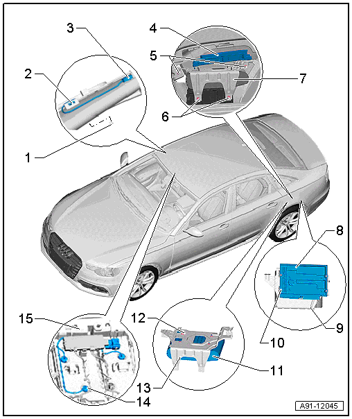
Speaker, Standard, BOSE, Sedan
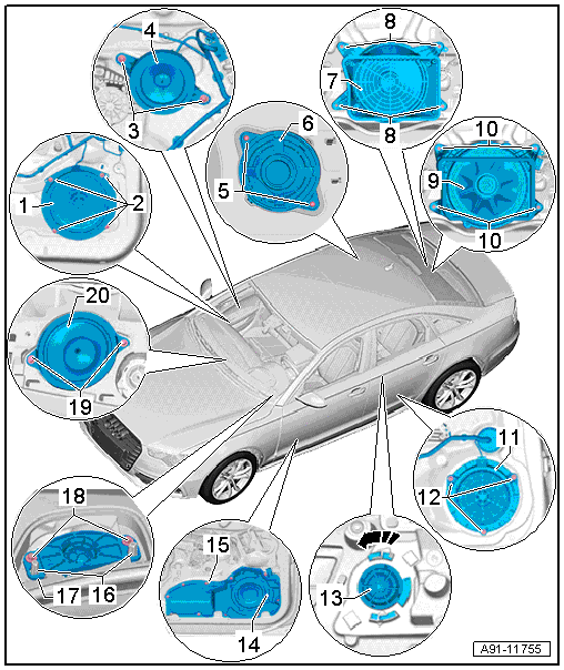
1 - Left Front Bass Speaker -R21-/Right Front Bass Speaker -R23-, Standard
- Removing and installing. Refer to → Chapter "Left/Right Front Bass Speaker -R21-/-R23-, Removing and Installing, Standard".
2 - Bolt
- 3 Nm
- Quantity: 4
3 - Bolt
- 3 Nm
- Quantity: 2
4 - Left Front Midrange Speaker -R103-/Right Front Midrange Speaker -R104-, BOSE
- Removing and installing. Refer to → Chapter "Left/Right Front Midrange Speaker -R103-/-R104-, Removing and Installing".
5 - Bolt
- 2 Nm
- Quantity: 2
6 - Left Effects Speaker -R209-/Right Effects Speaker -R210-, BOSE
- Removing and installing. Refer to → Chapter "Left/Right Effects Speaker -R209-/-R210-, Removing and Installing, BOSE".
7 - Subwoofer -R211-, Standard
- Removing and installing. Refer to → Chapter "Subwoofer -R211-, Removing and Installing, Standard".
8 - Bolt
- 3 Nm
- Quantity: 4
9 - Subwoofer -R211-, BOSE
- Removing and installing. Refer to → Chapter "Subwoofer -R211-, Removing and Installing, BOSE".
10 - Bolt
- 3 Nm
- Quantity: 4
11 - Left Rear Mid-Bass Speaker -R159-/Right Rear Mid-Bass Speaker -R160-
- Removing and installing. Refer to → Chapter "Left/Right Rear Mid-Bass Speaker -R159-/-R160-, Removing and Installing".
- Left Rear Bass Speaker -R15-/Right Rear Bass Speaker -R17-
- Removing and installing. Refer to → Chapter "Left/Right Rear Bass Speaker -R15-/-R17-, Removing and Installing".
12 - Bolt
- 3 Nm
- Quantity: 3
13 - Left Rear Treble Speaker -R14-/Right Rear Treble Speaker -R16-
- Removing and installing. Refer to → Chapter "Left/Right Rear Treble Speaker -R14-/-R16-, Removing and Installing".
14 - Left Front Bass Speaker -R21-/Right Front Bass Speaker -R23-, BOSE
- Removing and installing. Refer to → Chapter "Left/Right Front Bass Speaker -R21-/-R23-, Removing and Installing, BOSE".
15 - Bolt
- 3 Nm
- Quantity: 10
16 - Centering Pin
17 - Left Front Treble Speaker -R20-/Right Front Treble Speaker -R22-
- Removing and installing. Refer to → Chapter "Left/Right Front Treble Speaker -R20-/-R22-, Removing and Installing".
18 - Bolt
- 2 Nm
- Quantity: 2
19 - Bolt
- 2 Nm
- Quantity: 2
20 - Center Speaker -R208-
- Removing and installing. Refer to → Chapter "Center Speaker -R208-, Removing and Installing".
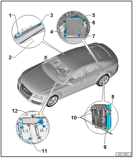
Speaker, Bang & Olufsen, Sedan
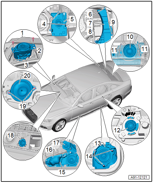
1 - Bolt
- 2 Nm
- Quantity: 2
2 - Right Front Treble Speaker -R22-/Left Front Treble Speaker -R20-
- With Left Front Treble Speaker Motor -V344-/Right Front Treble Speaker Motor -V345-
- Removing and installing. Refer to → Chapter "Front Treble Speaker -R20-/-V344-/-R22-/-V345-, Removing and Installing, Bang & Olufsen".
3 - Centering Pin
4 - Bolt
- 2 Nm
- Quantity: 3
5 - Left Effects Speaker -R209-/Right Effects Speaker -R210-
- Removing and installing. Refer to → Chapter "Left/Right Effects Speaker -R209-/-R210-, Removing and Installing, Bang & Olufsen".
6 - Bolt
- 5 Nm
7 - Subwoofer -R211-
- Removing and installing (from 02/18/2013). Refer to → Chapter "Subwoofer -R211-, Removing and Installing, Bang & Olufsen, Sedan from 02/18/2013".
8 - Nut
- 5 Nm
9 - Bolt
- 5 Nm
10 - Subwoofer -R211-
- Removing and installing (through 02/11/2013). Refer to → Chapter "Subwoofer -R211-, Removing and Installing, Bang & Olufsen, Sedan through 02/11/2013".
11 - Bolt
- 2 Nm
- Quantity: 4
12 - Left Rear Treble Speaker -R14-/Right Rear Treble Speaker -R16-
- Removing and installing. Refer to → Chapter "Left/Right Rear Treble Speaker -R14-/-R16-, Removing and Installing".
- Left Rear Midrange Speaker -R105-/Right Rear Midrange Speaker -R106-
- Removing and installing. Refer to → Chapter "Rear Midrange Speaker, Removing and Installing".
13 - Left Rear Midrange Speaker -R105-/Right Rear Midrange Speaker -R106-
- Removing and installing. Refer to → Chapter "Left/Right Rear Mid-Bass Speaker -R159-/-R160-, Removing and Installing, Bang & Olufsen".
- Left Rear Bass Speaker -R15-/Right Rear Bass Speaker -R17-
- Removing and installing. Refer to → Chapter "Left/Right Rear Bass Speaker -R15-/-R17-, Removing and Installing, Bang & Olufsen".
14 - Bolt
- 3 Nm
- Quantity: 3
15 - Left Front Bass Speaker -R21-/Right Front Bass Speaker -R23-
- Removing and installing. Refer to → Chapter "Front Bass Speakers -R21-/-R103-/-R23-/-R104-, Removing and Installing, Bang & Olufsen".
16 - Bolt/Nut
- 3 Nm
- Quantity 10/Quantity 2
17 - Left Front Midrange Speaker -R103-/Right Front Midrange Speaker -R104-
- Removing and installing. Refer to → Chapter "Left/Right Front Midrange Speaker -R103-/-R104-, Removing and Installing, Bang & Olufsen".
18 - Center Speaker 2 -R219-
- Removing and installing. Refer to → Chapter "Center Speaker 2 -R219-, Removing and Installing, Bang & Olufsen".
19 - Bolt
- 2 Nm
- Quantity: 2
20 - Center Speaker -R208-
- Removing and installing. Refer to → Chapter "Center Speaker -R208-, Removing and Installing".
Sound Amplifier, Microphones, BOSE, through MY 2014
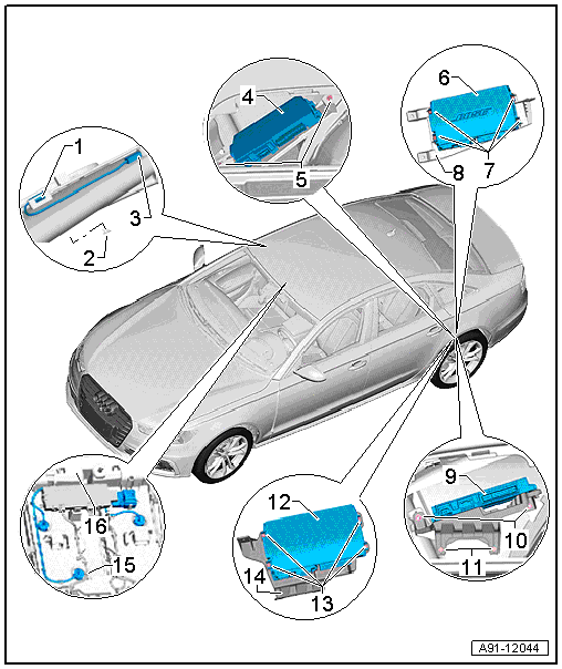
1 - ANC Microphone with Retaining Plate
- Quantity: 4
- Overview. Refer to → Chapter "Component Location Overview - ANC Microphones".
2 - Trim
- Quantity: 4
3 - Wiring Harness Coupling
- Quantity: 4
- Overview. Refer to → Chapter "Component Location Overview - ANC Microphones".
4 - Digital Sound System Control Module -J525-
- Connector assignment. Refer to → Chapter "Digital Sound System Control Module -J525-, BOSE, through MY 2014".
- RMC, Removing and Installing. Refer to → Chapter "Digital Sound System Control Module -J525-, Removing and Installing, BOSE, RMC, through MY 2014".
5 - Nut
- 4 Nm
- Quantity: 3
6 - Digital Sound System Control Module -J525-
7 - Bolt
- 6 Nm
- Quantity: 4
8 - Bracket
9 - Digital Sound System Control Module -J525-
- Removing and Installing (MMI). Refer to → Chapter "Digital Sound System Control Module -J525-, Removing and Installing, BOSE, MMI, through MY 2014".
10 - Nut
- 4 Nm
- Quantity: 2
11 - Bolt
- 4 Nm
- Quantity: 2
12 - Digital Sound System Control Module -J525-
13 - Bolt
- 6 Nm
- Quantity: 4
14 - Bracket
15 - Interior Microphone -R74-
- Overview. Refer to → Chapter "Overview - Microphone Unit".
16 - Front Interior Lamp -W1-
- With Microphone Unit in Front Roof Module -R164-
- Removing and installing. Refer to → Electrical Equipment; Rep. Gr.96; Controls; Front Interior/Reading Lamp, Removing and Installing.
Sound Amplifier, Microphones, Standard, BOSE, from MY 2015
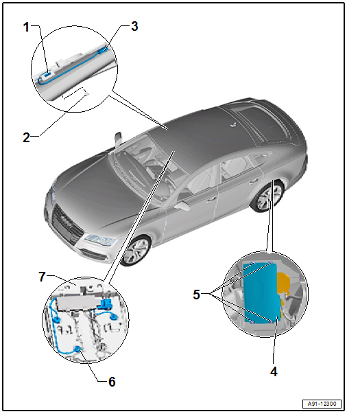
1 - ANC Microphone with Retaining Plate
- Quantity: 4
- Overview. Refer to → Chapter "Component Location Overview - ANC Microphones".
2 - Trim
- Quantity: 4
3 - Wiring Harness Coupling
- Quantity: 4
- Overview. Refer to → Chapter "Component Location Overview - ANC Microphones".
4 - Digital Sound System Control Module -J525-
- Connector assignment, Standard. Refer to → Wiring diagrams, Troubleshooting & Component locations.
- BOSE connector assignment. Refer to → Wiring diagrams, Troubleshooting & Component locations.
- Removing and installing. Refer to → Chapter "Digital Sound System Control Module -J525-, Removing and Installing, Standard and BOSE, from MY 2015".
5 - Bolt
- 4 Nm
- Quantity: 4
6 - Interior Microphone -R74-
- Overview. Refer to → Chapter "Overview - Microphone Unit".
7 - Front Interior Lamp -W1-
- With Microphone Unit in Front Roof Module -R164-
- Removing and installing. Refer to → Electrical Equipment; Rep. Gr.96; Controls; Front Interior/Reading Lamp, Removing and Installing.
Sound Amplifier, Microphones, Bang & Olufsen, through MY 2014
1 - Trim
- Quantity: 4
2 - ANC Microphone with Retaining Plate
- Quantity: 4
- Overview. Refer to → Chapter "Component Location Overview - ANC Microphones".
3 - Wiring Harness Coupling
- Quantity: 4
- Overview. Refer to → Chapter "Component Location Overview - ANC Microphones".
4 - Nut
- 5 Nm
5 - Digital Sound System Control Module -J525-
- Connector assignment. Refer to → Chapter "Digital Sound System Control Module -J525-, Bang & Olufsen, through MY 2014".
- Removing and installing. Refer to → Chapter "Digital Sound System Control Module -J525-, Removing and Installing, Bang & Olufsen, through MY 2014".
6 - Bracket
7 - Digital Sound System Control Module -J525-
8 - Bracket
9 - Bolt
- 3.5 Nm
10 - Digital Sound System Control Module 2 -J787-
- Connector assignment. Refer to → Chapter "Digital Sound System Control Module 2 -J787-, Bang & Olufsen, through MY 2014".
- Removing and installing. Refer to → Chapter "Digital Sound System Control Module 2 -J787-, Removing and Installing, Bang & Olufsen, through MY 2014".
11 - Bracket
12 - Nut
- 3.5 Nm
- Quantity: 4
13 - Bolt
- 3.5 Nm
14 - Interior Microphone -R74-
- Overview. Refer to → Chapter "Overview - Microphone Unit".
15 - Front Interior Lamp -W1-
- With Microphone Unit in Front Roof Module -R164-
- Removing and installing. Refer to → Electrical Equipment; Rep. Gr.96; Controls; Front Interior/Reading Lamp, Removing and Installing.
Sound Amplifier, Microphones, Bang & Olufsen, from MY 2015
1 - ANC Microphone with Retaining Plate
- Quantity: 4
- Overview. Refer to → Chapter "Component Location Overview - ANC Microphones".
2 - Trim
- Quantity: 4
3 - Wiring Harness Coupling
- Quantity: 4
- Overview. Refer to → Chapter "Component Location Overview - ANC Microphones".
4 - Nut
- Top: 5 Nm
- Bottom: 4 Nm
- Quantity: 3
5 - Bracket
6 - Bolt
- 5 Nm
7 - Digital Sound System Control Module -J525-
- Connector assignment. Refer to → Wiring diagrams, Troubleshooting & Component locations.
- Removing and installing. Refer to → Chapter "Digital Sound System Control Module -J525-, Removing and Installing, Bang & Olufsen, from MY 2015".
8 - Digital Sound System Control Module -J525-
9 - Bracket
10 - Bolt
- 4 Nm
- Quantity: 4
11 - Interior Microphone -R74-
- Overview. Refer to → Chapter "Overview - Microphone Unit".
12 - Front Interior Lamp -W1-
- With Microphone Unit in Front Roof Module -R164-
- Removing and installing. Refer to → Electrical Equipment; Rep. Gr.96; Controls; Front Interior/Reading Lamp, Removing and Installing.
No Illustration
- Brace bolts: 5 Nm
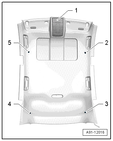
Component Location Overview - ANC Microphones
The ANC (active noise cancellation) system consists of four additional microphones inside the headliner and special software inside the Digital Sound System Control Module -J525-.
ANC microphones, through MY 2014
1 - Front Interior Lamp -W1- with Interior Microphone -R74-
2 - Left Center Microphone -R142-
3 - Left Rear Microphone -R144-
4 - Right Rear Microphone -R145-
5 - Right Center Microphone -R143-
ANC microphones, from MY 2015
1 - Front Interior Lamp -W1- with Interior Microphone -R74-
2 - Noise Reduction Microphone 1 -R285-
3 - Noise Reduction Microphone 3 -R287-
4 - Noise Reduction Microphone 4 -R288-
5 - Noise Reduction Microphone 2 -R286-
The ANC microphones have a trailing cable. The coupling is inside the headliner.
It is necessary to lower the headliner in order to remove the coupling.
ANC Microphones, Removing and Installing. Refer to → Chapter "ANC Microphones, Removing and Installing".
