Audi A6 Typ 4G: Connector Assignments
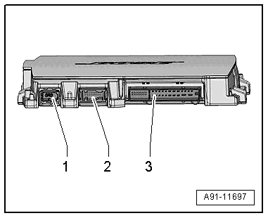
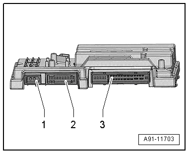
Digital Sound System Control Module -J525-, BOSE, through MY 2014
Digital Sound System Control Module -J525-
1 - MOST Bus
2 - 18-Pin Connector -T18-
3 - 38-Pin Connector -T38-
 Note
Note
Unlisted connector terminals are not assigned.
1 - MOST Bus
1 - Output
2 - Input
2 - 18-Pin Connector -T18-
6 - Left Rear Microphone -R144- (+)
7 - Left Rear Microphone -R144- (-)
8 - Right Rear Microphone -R145- (+)
9 - Right Rear Microphone -R145- (-)
10 - Speed signal from Engine Control Module -J623- (+)
11 - Speed signal from Engine Control Module -J623- (-)
13 - Right Center Microphone -R143- (+)
14 - Right Center Microphone -R143- (-)
16 - Left Center Microphone -R142- (+)
17 - Left Center Microphone -R142- ()
3 - 38-Pin Connector -T38-
1 - Terminal 30
2 - Terminal 31
3 - Right rear speaker (+)
4 - Left Front Bass Speaker -R21- (+)
5 - Subwoofer -R211- (-)
6 - Not Assigned
7 - Left Front Midrange Speaker -R103- (-)
8 - Right Front Midrange Speaker -R104- (+)
9 - Right Front Treble Speaker -R22- (-)
10 - Left Front Treble Speaker -R20- (+)
11 - Right Front Bass Speaker -R23- (-)
12 - Right Front Bass Speaker -R23- (+)
13 - Left rear speaker (+)
14 - Left rear speaker (-)
15 - Right rear speaker (-)
16 - Left Front Bass Speaker -R21- (-)
17 - Subwoofer -R211- (+)
18 - Not Assigned
19 - Left Front Midrange Speaker -R103- (+)
20 - Right Front Midrange Speaker -R104- (-)
21 - Right Front Treble Speaker -R22- (+)
22 - Left Front Treble Speaker -R20- (-)
23 - Not Assigned
24 - Not Assigned
25 - Ring-break Diagnostic Cable
26 - Not Assigned
27 - Not Assigned
28 - Ground shielding from Microphone Unit In Front Roof Module -R164-, Interior Microphone -R74-
29 - Microphone Unit in Front Roof Module -R164-, Interior Microphone -R74- (-)
30 - Microphone Unit in Front Roof Module -R164-, Interior Microphone -R74- (+)
31 - Center Speaker -R208- (+)
32 - Center Speaker -R208- (-)
33 - Left Effects Speaker -R209- (-)
34 - Left Effects Speaker -R209- (+)
35 - Not Assigned
36 - Not Assigned
37 - Right Effects Speaker -R210- (+)
38 - Right Effects Speaker -R210- (-)
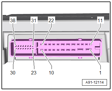
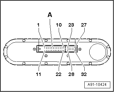
Digital Sound System Control Module -J525-, Bang & Olufsen, through MY 2014
Digital Sound System Control Module -J525-
1 - MOST Bus
2 - 32-Pin Connector -T32e-
3 - 38-Pin Connector -T38-
Note
Unlisted connector terminals are not assigned.
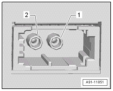
1 - MOST Bus
1 - Output
2 - Input
2 - 32-Pin Connector -T32e-
1 - Digital Sound System Control Module 2 -J787-
2 - Digital Sound System Control Module 2 -J787-
3 - Digital Sound System Control Module 2 -J787-
4 - Digital Sound System Control Module 2 -J787-
5 - Digital Sound System Control Module 2 -J787-
6 - Left Center Microphone -R142- (+)
7 - Right Center Microphone -R143- (+)
8 - Left Rear Microphone -R144- (+)
9 - Microphone Unit in Front Roof Module -R164-, Interior Microphone -R74- (+)
10 - Right Rear Microphone -R145- (+)
11 - Ground Shielding
12 - Speed signal from Engine Control Module -J623- (+)
13 - Not Assigned
14 - Digital Sound System Control Module 2 -J787-
15 - Not Assigned
16 - Digital Sound System Control Module 2 -J787-
17 - Digital Sound System Control Module 2 -J787-
18 - Digital Sound System Control Module 2 -J787-
19 - Digital Sound System Control Module 2 -J787-
20 - Digital Sound System Control Module 2 -J787-
21 - Digital Sound System Control Module 2 -J787-
22 - Left Center Microphone -R142- ()
23 - Right Center Microphone -R143- (-)
24 - Left Rear Microphone -R144- (-)
25 - Microphone Unit in Front Roof Module -R164-, Interior Microphone -R74- (-)
26 - Right Rear Microphone -R145- (-)
27 - Not Assigned
28 - Speed signal from Engine Control Module -J623- (-)
29 - Ring-break Diagnostic Cable
30 - Digital Sound System Control Module 2 -J787-
31 - Not Assigned
32 - Digital Sound System Control Module 2 -J787-
3 - 38-Pin Connector -T38-
1 - Terminal 30
2 - Terminal 31
5 - Left Front Midrange Speaker -R103- (+)
6 - Right Front Midrange Speaker -R104- (+)
7 - Center Speaker -R208- (+)
8 - Center Speaker 2 -R219- (+)
9 - Left Effects Speaker -R209- (+)
10 - Right Effects Speaker -R210- (+)
17 - Left Front Midrange Speaker -R103- (-)
18 - Right Front Midrange Speaker -R104- (-)
19 - Center Speaker -R208- (-)
20 - Center Speaker 2 -R219- (-)
21 - Left Effects Speaker -R209- (-)
22 - Right Effects Speaker -R210- (-)
23 - Left Front Treble Speaker -R20- (+)
24 - Right Front Treble Speaker -R22- (+)
25 - Left Rear Treble Speaker -R14- (+)
26 - Right Rear Treble Speaker -R16- (+)
31 - Left Front Treble Speaker -R20- (-)
32 - Right Front Treble Speaker -R22- (-)
33 - Left Rear Treble Speaker -R14- (-)
34 - Right Rear Treble Speaker -R16- (-)
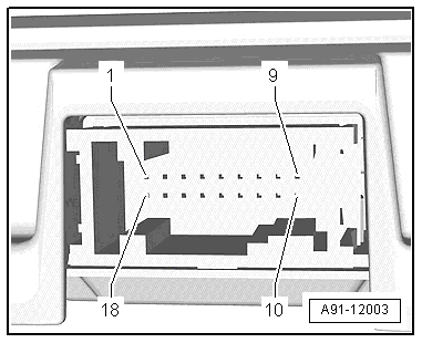
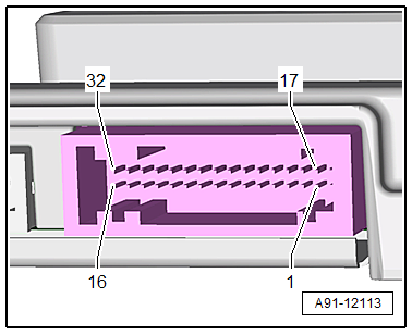
Digital Sound System Control Module 2 -J787-, Bang & Olufsen, through MY 2014
Digital Sound System Control Module 2 -J787-
1 - 32-Pin Connector -T32f-
Note
Unlisted connector terminals are not assigned.
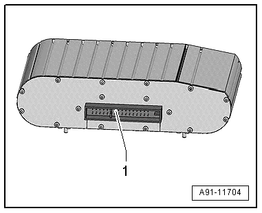
1 - 32-Pin Connector -T32f-
1 - Terminal 30
2 - Terminal 31
3 - Right Front Bass Speaker -R23- (+)
4 - Right Front Bass Speaker -R23- (-)
5 - Left Front Bass Speaker -R21- (+)
6 - Left Front Treble Speaker Motor -V344- (-)
7 - Left Front Treble Speaker Motor -V344-
8 - Digital Sound System Control Module -J525-
9 - Digital Sound System Control Module -J525-
10 - Digital Sound System Control Module -J525-
11 - Digital Sound System Control Module -J525-
12 - Digital Sound System Control Module -J525-
13 - Digital Sound System Control Module -J525-
14 - Digital Sound System Control Module -J525-
15 - Subwoofer -R211- (+)
16 - Subwoofer -R211- (-)
17 - Left Front Bass Speaker -R21- (-)
18 - Left Front Treble Speaker Motor -V344- (+)
19 - Right Front Treble Speaker Motor -V345-
20 - Digital Sound System Control Module -J525-
21 - Right Front Treble Speaker Motor -V345- (+)
22 - Right Front Treble Speaker Motor -V345- (-)
23 - Digital Sound System Control Module -J525-
24 - Digital Sound System Control Module -J525-
25 - Digital Sound System Control Module -J525-
26 - Digital Sound System Control Module -J525-
27 - Digital Sound System Control Module -J525-
28 - Right Rear Mid-Bass Speaker -R160- (+)
29 - Right Rear Mid-Bass Speaker -R160- (-)
30 - Digital Sound System Control Module -J525-
31 - Left Rear Mid-Bass Speaker -R159- (+)
32 - Left Rear Mid-Bass Speaker -R159- (-)