Audi A6 Typ 4G: Control Modules
Overview - Control Modules
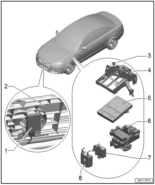
1 - Garage Door Opener Control Module -J530-
- Removing and installing. Refer to → Chapter "Garage Door Opener Control Module, Removing and Installing".
2 - Radiator Grille
3 - Nut
- 3 Nm
- Quantity: 2
4 - Mount
- For the Vehicle Electrical System Control Module -J519- and relay panel
- Removing and installing. Refer to → Chapter "Relay Panel Mount, Removing and Installing, Under Instrument Panel and Left Side, Vehicle Electrical System Control Module -J519-".
5 - Vehicle Electrical System Control Module -J519-
- Removing and installing. Refer to → Chapter "Vehicle Electrical System Control Module -J519-, Removing and Installing".
6 - Relay Carrier Under Left Instrument Panel
7 - Headlamp Range Control Module -J431-
8 - Mount
- For the Headlamp Range Control Module -J431-
Overview - Data Bus On Board Diagnostic Interface
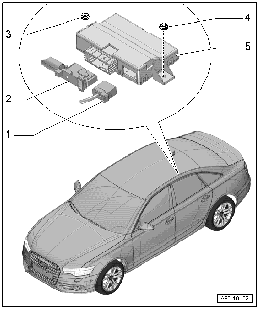
1 - Fiber Optic Cable Connector
- Seal with Fiber-Optic Repair Set - Connector Protective Caps -VAS6223/9-
2 - Connector
- For Data Bus On Board Diagnostic Interface -J533-
3 - Nut
- 2 Nm
4 - Nut
- 2 Nm
5 - Data Bus On Board Diagnostic Interface -J533-
- Removing and installing. Refer to → Chapter "Data Bus On Board Diagnostic Interface -J533-, Removing and Installing".
Vehicle Electrical System Control Module -J519-, Removing and Installing
- If the control module was replaced, select the "Replace" function for the respective control module in "Guided Fault Finding" or "Guided Functions" using the Vehicle Diagnostic Tester.
Removing
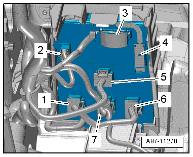
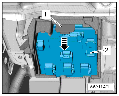
- Disengage the relay carrier under the instrument panel on the left side and the relay- and auxiliary fuse panels still connected to the mount. Refer to → Chapter "Relay Carrier under Left Instrument Panel, Removing and Installing".
- Disconnect the connectors -1, 2, 5, 6 and 7-.
- Disconnect the connectors -3 and 4-.
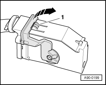
- To disconnect the connector, press the catch -1-, rotate the retaining bracket in the direction of the -arrow- and remove the connector.
- Release the spring -1- and remove the vehicle electrical system control module -2- downward in direction of -arrow-.
Installing
Install in reverse order of removal. Note the following:
- Install the relay carrier under the instrument panel on the left side. Refer to → Chapter "Relay Carrier under Left Instrument Panel, Removing and Installing".
Garage Door Opener Control Module, Removing and Installing
Removing
- Remove the lock carrier cover. Refer to → Body Exterior; Rep. Gr.63; Rear Bumper; Attachments, Removing and Installing.
- Release the tab -4- in direction of -arrow- and remove the control module -2- from the mount -3-.
- Disconnect the connector -1-.
Installing
Install in reverse order of removal.
Data Bus On Board Diagnostic Interface -J533-, Removing and Installing
Special tools and workshop equipment required
- Fiber-Optic Repair Set - Connector Protective Caps -VAS6223/9- from Fiber-Optic Repair Set -VAS6223B-
- If the control module was replaced, select the "Replace" function for the respective control module in "Guided Fault Finding" or "Guided Functions" using the Vehicle Diagnostic Tester.
Removing
- Remove the rear seat bench. Refer to → Body Interior; Rep. Gr.72; Rear Seats; Seat Bench/Single Seat, Removing and Installing.
- Fold back the front of the insulation mat.
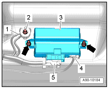
- Remove the nuts -arrows-, if equipped.
- Remove the data bus on board diagnostic interface -3- from the threaded pins.
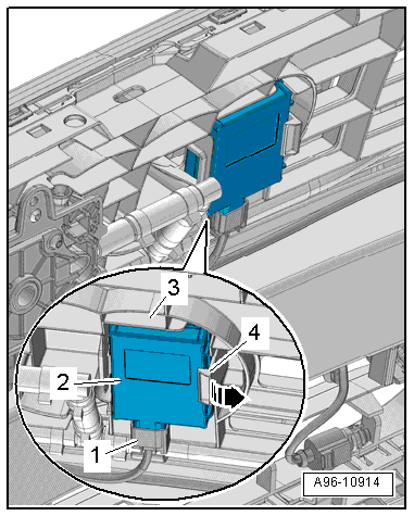
- Disconnect the connector -5- and the connector -4- for the fiber-optic cable.
 Note
Note
If the ground cable -1- is above the mount on the data bus on board diagnostic interface as illustrated, then it must be loosened on the ground distributor -2-.
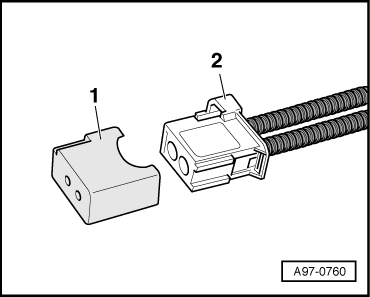
- Seal open wiring harness connector -2- with Fiber-Optic Repair Set - Connector Protective Caps - VAS6223/9--item 1-.
Note
The protective cap prevents contamination of or mechanical damage to end face of fiber optic cable which would impair signal transmission.
- To disconnect the connector, press the tab -1-, turn the retaining bracket in direction of the -arrow- and remove the connector.
Installing
Install in reverse order of removal. Note the following:
If the Data Bus On Board Diagnostic Interface -J533- was replaced, then it must be coded again using the Vehicle Diagnostic Tester.
