Audi A6 Typ 4G: Ground Cable with Battery Monitoring Control Module -J367-, Removing and Installing
Ground Cable with Battery Monitoring Control Module -J367-, Removing and Installing, Vehicles without High Voltage System
Removing
- Turn off the ignition.
- Lift the luggage compartment floor covering by the handle and fold it forward.
- Remove the vehicle tools.
- If equipped, remove the spare tire well trim. Refer to → Body Interior; Rep. Gr.70; Luggage Compartment Trim Panels; Spare Wheel Well Trim, Removing and Installing.
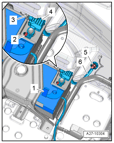
- Open the cover -1- over the battery negative terminal.
- Loosen the nut -2- several turns and remove the battery ground cable terminal from the battery negative pole.
- Disconnect the connector -3-.
- Remove the nut -5- and remove the ground cable -6- with the Battery Monitoring Control Module -J367--item 4-.
Installing
Install in reverse order of removal. Note the following:
- Connect the battery.
Ground Cable with Battery Monitoring Control Module -J367- for the Battery -A-, Removing and Installing, Vehicles with High Voltage System
 DANGER!
Damaged high voltage components may produce dangerously high voltage.
Note the following when working near high voltage components and cables:
- Do not use tools that have sharp edges, that are used for cutting or shaping, or that generate heat, such as welding, soldering, hot air or thermal adhesive equipment.
- Inspect the high voltage components in the area where the work will be performed before starting the procedure.
- Perform a visual inspection of the Electric Drive Power and Control Electronics -JX1-, the Electro-Drive Drive Motor -V141-, the Electrical A/C Compressor -V470- and the high voltage cables when working inside the engine compartment.
- Perform a visual inspection of the high voltage cables and the covers when working on the floor panel.
- Perform a visual inspection of the high voltage cables and the electro-box with the High Voltage System Maintenance Connector -TW- when working in the rear of the vehicle.
- Perform a visual inspection of all of the potential equalization cables.
Note the following when performing the visual inspection:
- None of the components may display any exterior damage.
- The high voltage cable insulation and the potential equalization cables may not be damaged.
- The high voltage cables may not be deformed in any way.
- Each high voltage component muss be labeled with a red warning label.
Removing
- Remove the luggage compartment floor. Refer to → Body Interior; Rep. Gr.70; Luggage Compartment Trim Panels; Luggage Compartment Floor Panel, Removing and Installing.
- Remove the battery exhaust air guide. Refer to → Heating, Ventilation, and Air Conditioning; Rep. Gr.87; Battery Cooling Module.
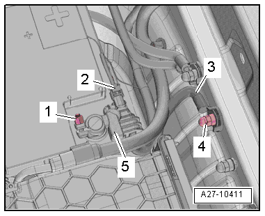
- Loosen the nut -1- several turns and remove the battery ground cable terminal from the battery pole.
- Disconnect the connector -2-.
- Remove the nut -5- and remove the ground cable -4- with Battery Monitoring Control Module -J367--item 3-.
Installing
Install in reverse order of removal. Note the following:
- Connect the battery.
Ground Cable with Battery Monitoring Control Module 2 -J934- for the Auxiliary Battery -A1-, Removing and Installing, Vehicles with High Voltage System
DANGER!
Damaged high voltage components may produce dangerously high voltage.
Note the following when working near high voltage components and cables:
- Do not use tools that have sharp edges, that are used for cutting or shaping, or that generate heat, such as welding, soldering, hot air or thermal adhesive equipment.
- Inspect the high voltage components in the area where the work will be performed before starting the procedure.
- Perform a visual inspection of the Electric Drive Power and Control Electronics -JX1-, the Electro-Drive Drive Motor -V141-, the Electrical A/C Compressor -V470- and the high voltage cables when working inside the engine compartment.
- Perform a visual inspection of the high voltage cables and the covers when working on the floor panel.
- Perform a visual inspection of the high voltage cables and the electro-box with the High Voltage System Maintenance Connector -TW- when working in the rear of the vehicle.
- Perform a visual inspection of all of the potential equalization cables.
Note the following when performing the visual inspection:
- None of the components may display any exterior damage.
- The high voltage cable insulation and the potential equalization cables may not be damaged.
- The high voltage cables may not be deformed in any way.
- Each high voltage component muss be labeled with a red warning label.
Removing
- Remove the luggage compartment floor. Refer to → Body Interior; Rep. Gr.70; Luggage Compartment Trim Panels; Luggage Compartment Floor Panel, Removing and Installing.
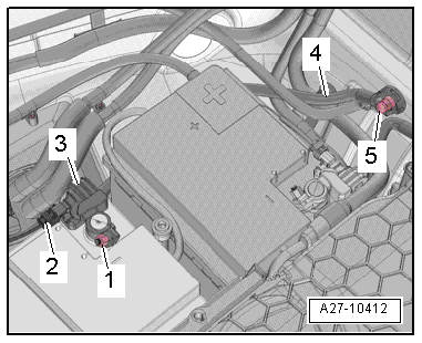
- Loosen the nut -1- several turns and remove the battery ground cable terminal from the battery pole.
- Disconnect the connector -2-.
- Remove nut -4- and ground cable -3- with the Battery Monitoring Control Module 2 -J934--item 5-.
Installing
Install in reverse order of removal. Note the following:
- Connect the battery.