Audi A6 Typ 4G: Differential
Left Flange Shaft, Removing and Installing
- The transmission is removed.
Description of the procedure, refer to → S tronic Transmission Internal Components; Rep. Gr.39; Differential; Left Flange Shaft, Removing and Installing.
Right Flange Shaft, Removing and Installing
Special tools and workshop equipment required
- Bearing/Bushing Installer - Multiple Use -VW295-
- Slide Hammer Set -VW771-
- Lifting Eyebolt -3368-
- Used Oil Collection and Extraction Unit -SMN372500-
- Grease, refer to the Parts Catalog.
- M10 nut, quantity: 2
Removing
- The transmission is installed.
- Remove the right front wheel.
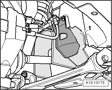
- Remove the right drive axle cover -1- inside the wheel housing.
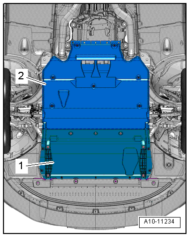
- Remove the rear noise insulation -2-, refer to → Body Exterior; Rep. Gr.66; Noise Insulation; Noise Insulation, Removing and Installing.
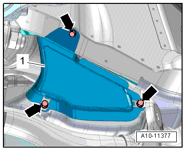
- Remove the bolts -arrows- and the right heat shield -1-.
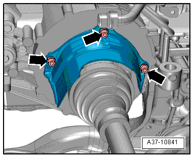
- Remove the bolts -arrows- and then remove the heat shield from the right drive axle.
- Remove the right drive axle from the transmission flange shaft and move it back.
- Place the Used Oil Collection and Extraction Unit -SMN372500- under the transmission.
- Install the Lifting Eyebolt -3368- into a threaded hole in the right flange shaft.
- Position the Slide Hammer Set -VW771- with the Slide Hammer Set -VW771/13- on the Lifting Eyebolt -3368- and remove the flange shaft.
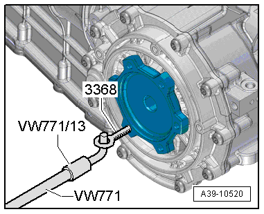
Installing
Install in reverse order of removal. Note the following:
 Note
Note
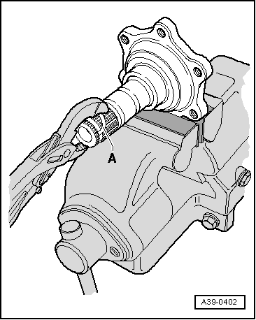
Replace the circlip on the right flange shaft.
- Clamp the flange shaft in a vise with jaw protectors. Remove the old circlip from the groove in the flange shaft using the new circlip -A-.
- Fill the space between the sealing- and dust lip half way with sealing grease, refer to the Parts Catalog.
- Drive in the right flange shaft using the Bearing/Bushing Installer - Multiple Use - VW295-.
- Check the transmission oil lever in the final drive and fill if necessary, refer to → Chapter "Transmission Fluid Level, Checking".
Center Differential
Overview - Center Differential
 Note
Note
- General Repair Instructions, refer to → Chapter "General Repair Information".
- Rules for cleanliness when working on the S tronic transmission, refer to → Chapter "Guidelines for Clean Working Conditions".
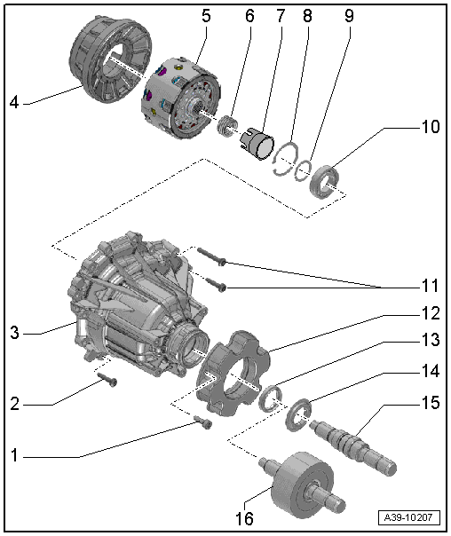
1 - Bolt
- Tightening specification, refer to → Rep. Gr.39; Center differential.
2 - Bolt
- Aluminum bolts
- Quantity 11
- Tightening specification, refer to → Rep. Gr.39; Center differential.
3 - Housing
- For the center differential
- Refer to → Chapter "Center Differential, Removing and Installing"
4 - Gear Carrier
- Installed position: The tab must fit into the cut-out in the transmission housing.
5 - Center Differential
6 - Pressure Spring
7 - Assembly Sleeve
- Does not have to be installed again
8 - Locking Ring
- For the transmission output shaft ball bearing with splines
- Removing and Installing, refer to → Rep. Gr.39; Center Differential.
9 - Locking Ring
- For the transmission output shaft with splines
- Removing and Installing, refer to → Rep. Gr.39; Center Differential.
10 - Ball Bearing
- For the transmission output shaft with splines
- Removing and Installing, refer to → Rep. Gr.39; Center Differential.
11 - Bolt
- Steel bolts
- Quantity: 2
- Tightening specification, refer to → Rep. Gr.39; Center Differential.
12 - Balance Weight
- Installed depending on the version
13 - Shaft Seal
- Replacing, refer to → Rep. Gr.39; Center Differential
14 - Dust Ring
- Replace after removing
15 - Transmission Output Shaft with Splines without Vibration Damper
- Allocation, refer to the Parts Catalog.
- Removing and Installing, refer to → Rep. Gr.39; Center Differential.
16 - Transmission Output Shaft with Splines and Vibration Damper
- Allocation, refer to the Parts Catalog.
- Removing and Installing, refer to → Rep. Gr.39; Center Differential.
- Installing the vibration damper, refer to → Rep. Gr.39; Center Differential.
Center Differential, Removing and Installing
Special tools and workshop equipment required
- Engine and Gearbox Jack -VAS6931-
- Used Oil Collection and Extraction Unit -SMN372500-
- Engine/Gearbox Jack - Gearbox Support -T10337-
- Sealant, refer to the Parts Catalog.
Removing
- The transmission is installed.
- Remove the driveshaft, refer to → Rep. Gr.39; Removal and Installation.
- Remove the subframe crossbrace, refer to → Suspension, Wheels, Steering; Rep. Gr.40; Subframe; Subframe Crossbrace, Removing and Installing.
 Caution
The suspension components could be damaged.
Do not rest the vehicle on its wheels if the subframe mount, the steering gear or the subframe crossbrace are not installed correctly.
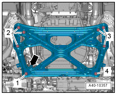
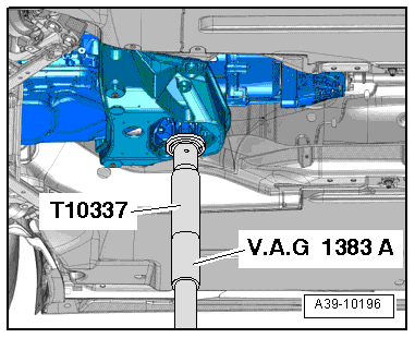
- Mount the Engine/Gearbox Jack - Gearbox Support -T10337- on the Engine and Gearbox Jack -VAS6931- and attach it under the transmission mount.
- Lift the transmission slightly using the Engine and Gearbox Jack -VAS6931-.
 WARNING
There is the risk of an accident.
The Engine and Gearbox Jack -VAS6931- may only be used during assembly and must not sit unsupervised under the vehicle.
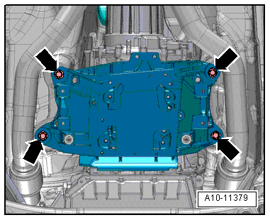
- Remove the bolts from the tunnel crossmember -arrows-.
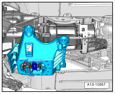
- Lower the transmission to dimension -a- using the Engine and Gearbox Jack -VAS6931-.
- Dimension -a- = maximum 70 mm.
- Place the Used Oil Collection and Extraction Unit -SMN372500- under the transmission.
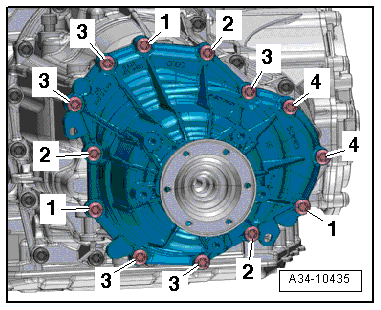
- Remove the bolts -1 through 4- and carefully remove the center differential housing. The transmission fluid (MTF) will leak out while doing this.
 Caution
Danger of damaging the center differential.
- Carefully and slowly pull center differential housing off of transmission toward rear. Otherwise the center differential can fall out of the transmission.
- A center differential that has fallen out may not be installed.
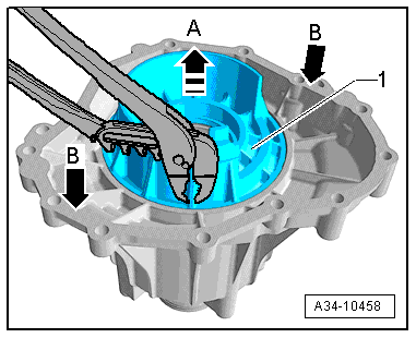
If the gear carrier -1- remains in the center differential housing, proceed as follows:
 Caution
Danger of damaging the sealing surface on the center differential housing.
Use a hammer to hit the housing carefully on several places.
- Hold the gear carrier -1- by one of the side ribs with pliers and remove it in -arrow A-.
- Using a Rubber Hammer, tap the housing on alternating sides -B arrows-.
Installing
Install in reverse order of removal. Note the following:
 Note
Note
Replace the bolts for the center differential housing.
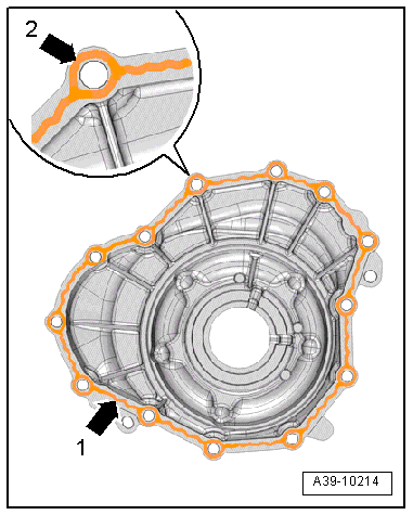
- Clean both housing separating surfaces thoroughly. They must be free of oil and grease.
- Apply a bead sealant -arrow 1- evenly and not too thick on the housing surfaces; sealant, refer to the Parts Catalog.
- Place a sealing ring round each bolt hole to prevent contact corrosion -arrow 2-.
- Coat the gear carrier surfaces with transmission fluid (MTF).
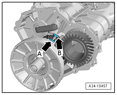
- Coat both outer ring surfaces on the gear carrier slightly with transmission fluid (MTF).
- Insert the gear carrier.
- Installed position: The tab on the gear carrier -arrow A- must fit into the opening in the transmission housing -arrow B-.
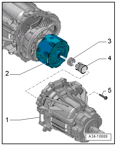
- Place the center differential -2- on the transmission -1-.
- Mount the guide sleeve -4- on the center differential.
- Install the pressure spring -3- into the center differential.
- Press the center differential housing centrally on until it makes contact with the transmission housing and hold it securely.
- Tighten the bolts for the center differential housing, refer to → S tronic Transmission Internal Components; Rep. Gr.39; Center differential.
- Install the driveshaft, refer to → Rep. Gr.39; Removal and Installation.
- Fill the transmission fluid (MTF).
Tightening Specifications
- Subframe crossbrace, refer to → Suspension, Wheels, Steering; Rep. Gr.40; Subframe; Overview - Subframe.

Transmission Output Shaft Seal, Replacing
Description of the procedure, refer to → Rep. Gr.39; Center differential; Transmission Output Shaft Seal, Replacingv

