Audi A6 Typ 4G: Door, Adjusting
Special tools and workshop equipment required
- Gauge - Gap Adjustment -3371-
- Front and Rear Door Template -T40038 /14-
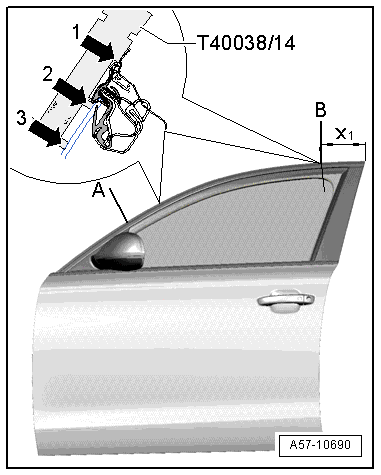
- Use the Front and Rear Door Template -T40038 /14- on the front door with the side -A- for the front measuring point on the B-pillar or -B- for the rear measuring point on the B-pillar.
- The "min and max" markings are used to check the lateral adjustment.
- The cut-outs in the template are used for checking height.
- The 0.6 mm graduation on the ends of the template is used for checking the recess of the front door to the fender, or of the rear door to the front door.
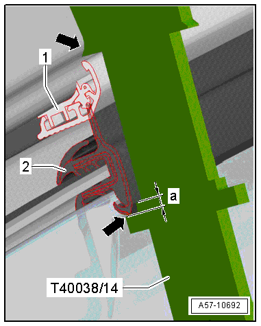
Height Adjustment, Checking using the Front and Rear Door Template -T40038 /14-.
- Place the template on the roof.
- The template must be touching the top of the roof and the trim molding -1- as illustrated -arrow-.
- The height is adjusted correctly when the bottom of the window guide -2- is inside the cut-out; a = 2 mm -arrow-.
Side Adjustment, Checking using the Front and Rear Door Template -T40038 /14-.
 Note
Note
- The template is 200 mm in total for exact positioning.
- The template must be positioned on the check point -B- in this distance.
- Place the template on check point -B- at -x1- = 200 mm, or on check point -A-.
- The template must be touching points -1- and -3- when the "min" adjustment is correct.
- The template may have a small gap at point -2-.
- The template must be touching points -2- and -3- when the "max" adjustment is correct.
- The template may have a small gap at point -1-.
Gap Dimensions
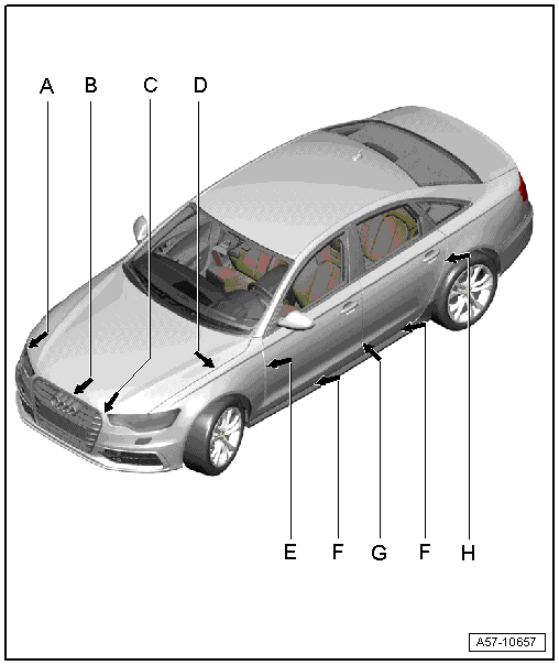
Note
The parallel alignment of the gap must not exceed 0.5 mm.
- Dimension -E- = 3.5 mm
- Dimension -F- = 5.0 mm
- Dimension -G- = 4.5 mm
- Dimension -H- = 3.5 mm
Driver Side:
- Remove the driver side instrument panel cover. Refer to → Body Interior; Rep. Gr.68; Storage Compartments and Covers; Driver Side Instrument Panel Cover, Removing and Installing.
- Remove the lower B-pillar trim. Refer to → Body Interior; Rep. Gr.70; Passenger Compartment Trim; A-Pillar Trim Panel, Removing and Installing.
- Remove the driver side relay carrier mount. Refer to → Electrical Equipment; Rep. Gr.97; Relay Carriers, Fuse Panels and E-Boxes; Overview - Relay Carriers, Fuse Panels and E-Boxes.
Front Passenger Side:
- Remove the glove compartment. Refer to → Body Interior; Rep. Gr.68; Storage Compartments and Covers; Glove Compartment, Removing and Installing.
On Both Sides:
- Remove the connector station from the A-pillar. Refer to → Electrical Equipment; Rep. Gr.97; Connectors; Left A-Pillar Connector Station, Removing and Installing.
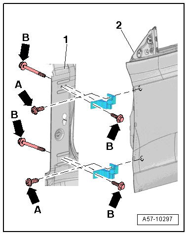
Adjustment in Longitudinal Direction
- Loosen the bolts -B arrows- on the top and bottom of the hinge and on the A-pillar -item 1-.
- Adjust the door -2- lengthwise.
- Tighten the bolts -B arrows-.
Adjustment to Center of Vehicle
Note
- The bolt -A- is a fitting bolt so it is generally not necessary to adjust the door using it.
- If it is necessary to make an adjustment using these bolts, the bolt can be replaced with one of the same length and strength category.
- Loosen the bolts -A arrows- on the top and bottom of the hinge.
- Adjust the door -2- lengthwise.
- Tighten the bolts -A arrows-.
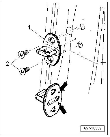
Catch, Adjusting
Note
- The striker pin backing must be position with the pins -arrows- exactly in the hole.
- The striker pins must be sheared off cleanly after sliding the striker pin.
- Loosen the bolts -2-.
- Slide the catch -1- until the door is flush with the body contours.
Note
- When adjusting the catch, move it only toward the center of the vehicle.
- Do not adjust the door height using the catch because the door lock will be damaged.
- The catch must align in door lock center for correct adjustment.
- Tighten the bolts -2-.