Audi A6 Typ 4G: E-Box, Removing and Installing
E-Box, Removing and Installing
Removing
- With the ignition switched off, disconnect the ground cable from the battery. Refer to → Chapter "Battery, Disconnecting and Connecting".
- Remove the washer fluid reservoir filler neck. Refer to → Chapter "Washer Fluid Reservoir Filler Tube, Removing and Installing".
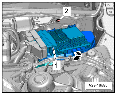
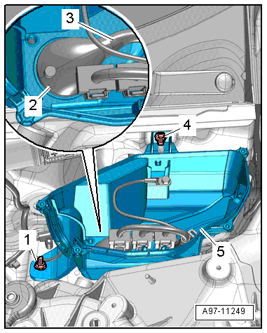
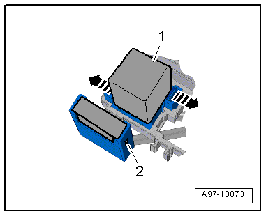
- Release the retainer -arrow-, remove the engine control module -1- and move it to the side with the wires still connected.
 Note
Note
Disregard -item 2-.
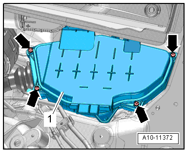
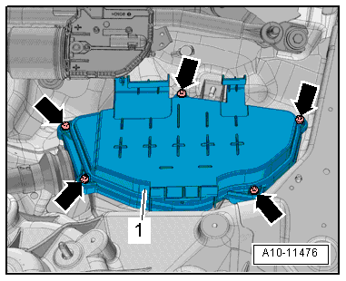
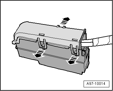
- Remove the bolts -arrows- and remove the cover -1- for the plenum chamber E-box.
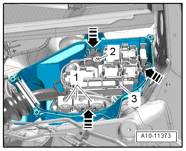
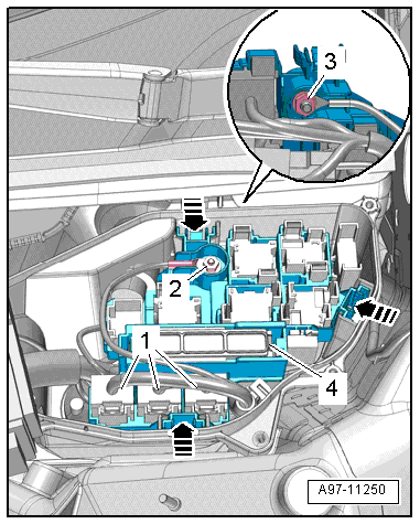
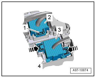
- Disconnect the connectors -1- and remove the nut -2- for the electric wire.
- Open the retainers in direction of -arrow- and remove the relay carrier with the fuse panel -3- and set aside.
- Remove the nuts -1 and 4- and disengage the plenum chamber E-box -5- from the threaded pins.
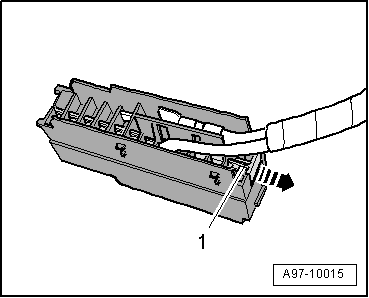
- Push the rubber grommet -2- toward the outside and guide the wiring harness -3- out, then remove the plenum chamber E-box upward.
Installing
Install in reverse order of removal. Note the following:
- Install the relay and fuse panel. Refer to → Chapter "Relay and Fuse Panel in Plenum Chamber E-Box, Removing and Installing".
E-Box Relay and Fuse Panels, Removing and Installing
Relay and Fuse Panel in Plenum Chamber E-Box, Removing and Installing
Removing
- With the ignition switched off, disconnect the ground cable from the battery. Refer to → Chapter "Battery, Disconnecting and Connecting".
- Remove the washer fluid reservoir filler neck. Refer to → Chapter "Washer Fluid Reservoir Filler Tube, Removing and Installing".
- Release the retainer in direction of -arrow-, remove the engine control module -1- and move it to the side with the wires still connected.
Note
Disregard -item 2-.
- Remove the bolts -arrows- and remove the cover -1- for the plenum chamber E-box.
- Disconnect the connectors -1- and remove the nut -2- for the electric wire.
- Open the retainers -arrow- and remove the relay carrier with the fuse panel -4- and set aside.
- Remove the nut -3- for the electric wire.
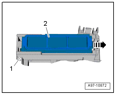
- Release the tab -arrow-, push fuse panel A -2- to the rear and disengage it from the relay panel -1-.
- Open the clip and remove the auxiliary fuse panel -2-.
- Release the clips -arrows- and remove the relay -1- and the control modules from the relay carriers.
- Release the retaining clips in direction of -arrows- and press the relay carrier -3- back and out of the bracket -4-.
- Open the clip -2- and remove the connector -1-.
Installing
Install in reverse order of removal. Note the following:
- Connect the battery. Required steps: vehicles without high voltage system. Refer to vehicles with high voltage system.
Fuse Panel A -SA-, Removing and Installing, in Plenum Chamber E-box
Removing
- Remove the relay panel and fuse panel and move them to the side with the relay and fuse panels still connected. Refer to → Chapter "E-Box Relay and Fuse Panels, Removing and Installing".
- Release the tab in direction of -arrow-, push fuse panel A -2- to the rear and disengage it from the fuse panel -1-.
- Unlock the release and remove it from the fuse carrier.
- Remove the fuses from the fuse carrier.
- Open the clips in direction of -arrows- and remove the fuse carrier cover.
- Pull off retaining strip -1- for the connectors -arrow- and remove the connectors from the plug-in socket
Note
Check the exact connector assignment in the current wiring diagram → Wiring diagrams, Troubleshooting & Component locations.
Installing
Install in reverse order of removal.
Suppressor -C24-, Removing and Installing
Removing
- Remove the relay panel and fuse panel and move them to the side with the relay and fuse panels still connected. Refer to → Chapter "E-Box Relay and Fuse Panels, Removing and Installing".
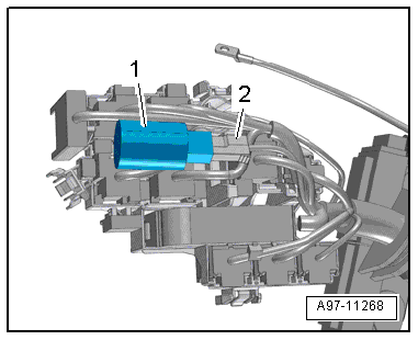
- Disconnect the connector -2-.
- Cut the cable tie, if equipped.
- Remove the suppressor -1-.
Installing
Install in reverse order of removal.