Audi A6 Typ 4G: Wire Junction, Removing and Installing
Terminal 30 Wire Junction -TV2-, Removing and Installing
Removing
- With the ignition switched off, disconnect the ground cable from the battery. Refer to → Chapter "Battery, Disconnecting and Connecting".
- Remove the tower brace. Refer to → Suspension, Wheels, Steering; Rep. Gr.40; Suspension Strut and Upper Control Arm; Tower Brace, Removing and Installing.
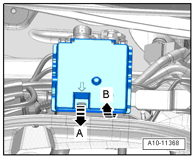
- Release the retainer in direction of -arrow A- and open the cover in direction of -arrow B-.
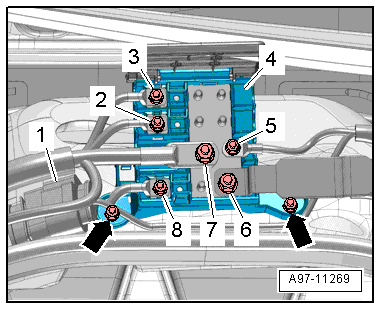
- Remove the wires -2, 3, 5, 6, 7 and 8-.
- Disconnect the connector -1-.
- Remove the nuts -arrows- and remove the wire junction from the plenum chamber bulkhead.
Installing
Install in reverse order of removal. Note the following:
- Connect the battery. Required steps: vehicles without high voltage system. Refer to vehicles with high voltage system.
Terminal 30 Wire Junction 2 - TV22-, Removing and Installing, with High Voltage System
 DANGER!
Damaged high voltage components may produce dangerously high voltage.
Note the following when working near high voltage components and cables:
- Do not use tools that have sharp edges, that are used for cutting or shaping, or that generate heat, such as welding, soldering, hot air or thermal adhesive equipment.
- Inspect the high voltage components in the area where the work will be performed before starting the procedure.
- Perform a visual inspection of the Electric Drive Power and Control Electronics -JX1-, the Electro-Drive Drive Motor -V141-, the Electrical A/C Compressor -V470- and the high voltage cables when working inside the engine compartment.
- Perform a visual inspection of the high voltage cables and the covers when working on the floor panel.
- Perform a visual inspection of the high voltage cables and the electro-box with the High Voltage System Maintenance Connector -TW- when working in the rear of the vehicle.
- Perform a visual inspection of all of the potential equalization cables.
Note the following when performing the visual inspection:
- None of the components may display any exterior damage.
- The high voltage cable insulation and the potential equalization cables may not be damaged.
- The high voltage cables may not be deformed in any way.
- Each high voltage component muss be labeled with a red warning label.
Removing
- Turn off the ignition and disconnect the ground cable from the batteries. Refer to → Chapter "Battery -A- and Auxiliary Battery -A1-, Disconnecting and Connecting, Vehicles with High Voltage System".
- Remove the coolant expansion tank and set it to the side with the coolant hose still connected.
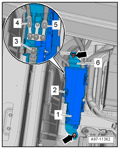
- Release the spring -2- and open the door -1-.
- Remove wires -3, 4 and 5-.
- Remove the nuts -arrows-.
- Remove the wire junction -6-.
Installing
Install in reverse order of removal. Note the following:
- Connect the battery. Required actions.
Wire Junction -TV1-, Removing and Installing, with High Voltage System
Removing
- With the ignition switched off, disconnect the ground cable from the battery. Refer to → Chapter "Battery -A- and Auxiliary Battery -A1-, Disconnecting and Connecting, Vehicles with High Voltage System".
- Remove the battery inlet air guide. Refer to → Heating, Ventilation, and Air Conditioning; Rep. Gr.87; Battery Cooling Module.
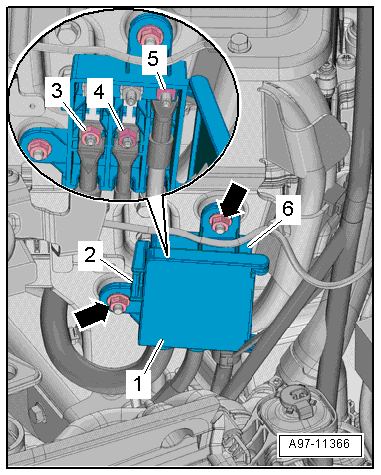
- Release the retaining spring -2- and open the door -1- over the wire junction.
- Remove wires -3, 4 and 5-.
- Remove the nuts -arrows-.
- Move the wire junction -6- upward as far as possible.
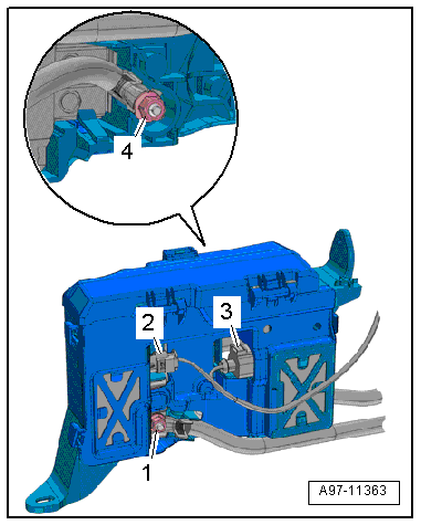
- Disconnect the electric wires -2 and 3-.
- Disconnect the positive wires -1 and 4-.
- Remove the wire junction.
- If the wire junction is being replaced:
- Remove the Starter Battery Switch-Over Relay -J580-. Refer to → Chapter "Starter Battery Switch-Over Relay -J580-, Removing and Installing".
- Remove the Battery Cut-Out Relay -J7-. Refer to → Chapter "Battery Cut-Out Relay -J7-, Removing and Installing".
- Remove the fuse.
Installing
Install in reverse order of removal. Note the following:
- Connect the battery. Required actions.