Audi A6 Typ 4G: Flushing Circuit Block Diagrams
 Note
Note
- The arrows in the following illustrations show the direction of refrigerant flow during flushing (refrigerant flows in opposite direction of flow when Air Conditioning (A/C) system is in operation while flushing, therefore the high pressure side of the A/C service system is connected to the low pressure connection of the refrigerant circuit to the A/C compressor).
- These block diagrams indicate a refrigerant circuit with restrictor and reservoir and a refrigerant circuit with expansion valve, receiver/dryer and a second evaporator (optional equipment on certain vehicles)
- Depending on the construction of the A/C service station, check valves may be installed between the refrigerant circuit and the A/C service station (to guarantee the correct direction of refrigerant flow during flushing).
Flushing circuit on vehicles with a high-voltage system
Refrigerant Circuit with Restrictor and Reservoir.
Refrigerant Circuit with Expansion Valve, Receiver/Dryer and Second Evaporator.
Vehicles with high-voltage system (without additional functions of the A/C system for example on the Audi A3 e-tron, Q5 hybrid etc.).
Vehicles with a high-voltage system (with additional functions of the A/C system such as heat pump operation for example on the Audi Q7 e-tron etc.).
Refrigerant Circuit with Restrictor and Reservoir
Note
On vehicles with a restrictor and reservoir, the restrictor and reservoir are removed, the lines disconnected for removing the restrictor are reconnected. The pipe connections to the removed reservoir are connected with each other via two adapters and the Refrigerant Circuits Adapter Set 2 - Adapter 31 -VAS6338/31- (from the Refrigerant Circuits Adapter Set 1 -VAS6338/1-).
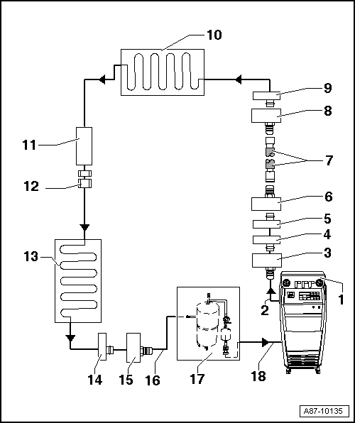
1 - A/C Service Station
- With electronics and a flushing program, for example A/C Service Station With Flushing Device. Refer to the Parts Catalog (Tools; Special Tools and Equipment: A/C and Heating).
- If an A/C service station without a flushing program is used, the procedure must be performed manually (evacuate, flush three times with at least 4 kg refrigerant each and extract refrigerant again, evacuate).
2 - A/C Service Station Refrigerant Hose
- From high pressure side of A/C service station (mostly colored red) to low pressure side connection of A/C compressor on refrigerant circuit (larger diameter).
3 - Adapter for Connecting Low Pressure Side to Refrigerant Circuit
- There are different versions depending on vehicle. Refer to → Chapter "Adapter for Assembling Flushing Circuit".
- From the Refrigerant Circuits Adapter Set 1 -VAS6338/1-
4 - Low Pressure Side Connection on Refrigerant Circuit
- There are different versions depending on vehicle. Refer to → Chapter "Adapter for Assembling Flushing Circuit".
- On refrigerant line from A/C compressor to reservoir
5 - Connection to Reservoir
- There are different versions depending on vehicle. Refer to → Chapter "Adapter for Assembling Flushing Circuit".
- On refrigerant line from A/C compressor to reservoir
6 - Adapter for Bridging the Removed Reservoir
- There are different versions depending on vehicle. Refer to → Chapter "Adapter for Assembling Flushing Circuit".
- From the Refrigerant Circuits Adapter Set 1 -VAS6338/1-
7 - Refrigerant Charge Hose
- For example Refrigerant Circuits Adapter Set 1 - Adapter 31 -VAS6338/31- (from the Refrigerant Circuits Adapter Set 1 -VAS6338/1-)
8 - Adapter for Bridging the Removed Reservoir
- There are different versions depending on vehicle. Refer to → Chapter "Adapter for Assembling Flushing Circuit".
- From the Refrigerant Circuits Adapter Set 1 -VAS6338/1-
9 - Connection to Reservoir
- There are different versions depending on vehicle. Refer to → Chapter "Adapter for Assembling Flushing Circuit".
10 - Evaporator
11 - Component Location of Restrictor
- Restrictor is removed.
- Remove the restrictor. Refer to → Heating, Ventilation and Air Conditioning; Rep. Gr.87; System Overview - Refrigerant Circuit (vehicle-specific repair manual).
12 - Bolts in Refrigerant Line
- Bolt together again after removing restrictor. Refer to → Heating, Ventilation and Air Conditioning; Rep. Gr.87; System Overview - Refrigerant Circuit (vehicle-specific repair manual).
13 - Condenser
14 - High Pressure Side Connection on Refrigerant Circuit
- There are different versions depending on vehicle. Refer to → Chapter "Adapter for Assembling Flushing Circuit".
15 - Adapter to Connection for High Pressure Side on Refrigerant Circuit
- There are different versions depending on vehicle. Refer to → Chapter "Adapter for Assembling Flushing Circuit".
- From the Refrigerant Circuits Adapter Set 1 -VAS6338/1-
16 - Charge Hose for Refrigerant Circuit Flushing Device
- From connection to the high pressure side of the A/C compressor on the refrigerant circuit (smaller diameter) to input of refrigerant circuit flushing device.
17 - Flushing Equipment for Refrigerant Circuits
- There are different versions of the Refrigerant Circuit Flushing Device. Refer to the Parts Catalog (Tools; Special Tools and Equipment: A/C and Heating).
- With filter, viewing glass, safety valve, heating, refrigerant container etc. (depending on version).
- Depending on the construction of the A/C service station and of refrigerant circuit flushing device, a check-valve may be installed at output of refrigerant circuit flushing device (to guarantee correct direction of refrigerant flow during flushing).
18 - A/C Service Station Refrigerant Hose
- From the low pressure side of the service station (mostly blue) to the output of the flushing device for refrigerant circuits.
Refrigerant Circuit with Expansion Valve, Receiver/Dryer and Second Evaporator
Note
- This block diagram shows a refrigerant circuit with expansion valve, receiver/dryer and second evaporator (optional equipment on certain vehicles).
- On vehicles with an expansion valve and receiver/dryer, the expansion valve is removed and replaced by an adapter. Depending on the vehicle, the receiver/dryer must also be removed and line connections to fluid reservoir be connected to each other by two adapters and a charge hose.
- On a vehicle with only one evaporator, components from -16- are not present or are not needed.
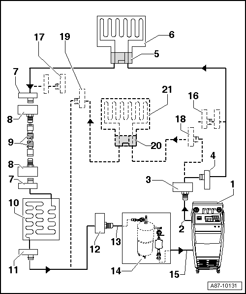
1 - A/C Service Station
- With electronics and a flushing program, A/C Service Station With Flushing Device. Refer to the Parts Catalog (Tools; Special Tools and Equipment: A/C and Heating).
- If an A/C service station without a flushing program is used, the procedure must be performed manually (evacuate, flush three times with at least 4 kg refrigerant each and extract refrigerant again, evacuate).
2 - A/C Service Station Refrigerant Hose
- From high pressure side of A/C service station (mostly colored red) to low pressure side connection of A/C compressor on refrigerant circuit (larger diameter).
3 - Adapter for Connecting Low Pressure Side to Refrigerant Circuit
- There are different versions depending on vehicle. Refer to → Chapter "Adapter for Assembling Flushing Circuit".
- From the Refrigerant Circuits Adapter Set 1 -VAS6338/1-
4 - Low Pressure Side Connection on Refrigerant Circuit
- There are different versions depending on vehicle. Refer to → Chapter "Adapter for Assembling Flushing Circuit".
5 - Adapter for the Removed Expansion Valve
- There are different versions depending on vehicle. Refer to → Chapter "Adapter for Assembling Flushing Circuit".
- From the Refrigerant Circuits Adapter Set 1 -VAS6338/1-
6 - Evaporator
7 - Connection to Receiver/Dryer
- There are different versions depending on vehicle. Refer to → Chapter "Adapter for Assembling Flushing Circuit".
- Neither installed on vehicles with dryer cartridge in receiver/dryer at condenser nor with receiver/dryer installed in condenser. Refer to → Heating, Ventilation and Air Conditioning; Rep. Gr.87; System Overview - Refrigerant Circuit (vehicle-specific repair manual).
8 - Adapter for Bridging the Removed Receiver/Dryer
- Not required for all vehicles.
- There are different versions depending on vehicle. Refer to → Chapter "Adapter for Assembling Flushing Circuit".
- From the Refrigerant Circuits Adapter Set 1 -VAS6338/1-
9 - Refrigerant Charge Hose
- For example Refrigerant Circuits Adapter Set 1 - Adapter 31 -VAS6338/31- (from the Refrigerant Circuits Adapter Set 1 -VAS6338/1-)
10 - Condenser
- If a receiver/dryer with dryer cartridge is installed at the condenser, the dryer cartridge must be removed (reseal receiver/dryer at or in condenser). Refer to → Heating, Ventilation and Air Conditioning; Rep. Gr.87; System Overview - Refrigerant Circuit or (vehicle-specific repair manual).
- If the receiver/dryer is directly installed at the condenser, the receiver/dryer must be removed and replaced only after flushing. Refer to → Heating, Ventilation and Air Conditioning; Rep. Gr.87; System Overview - Refrigerant Circuit (vehicle-specific repair manual).
Note
On certain vehicles the receiver/dryer is integrated inside the condenser and the dryer cartridge cannot be replaced separately and is not available as a single part. Replace the condenser with the receiver/dryer or dryer cartridge after flushing on these vehicles. Refer to → Heating, Ventilation and Air Conditioning; Rep. Gr.87; System Overview - Refrigerant Circuit and the Parts Catalog.
11 - High Pressure Side Connection on Refrigerant Circuit
- There are different versions depending on vehicle. Refer to → Chapter "Adapter for Assembling Flushing Circuit".
12 - Adapter to Connection for High Pressure Side on Refrigerant Circuit
- There are different versions depending on vehicle. Refer to → Chapter "Adapter for Assembling Flushing Circuit".
- From the Refrigerant Circuits Adapter Set 1 -VAS6338/1-
13 - Charge Hose for Refrigerant Circuit Flushing Device
- From connection to the high pressure side of the A/C compressor on the refrigerant circuit (smaller diameter) to input of refrigerant circuit flushing device.
14 - Flushing Equipment for Refrigerant Circuits
- There are different versions of the Refrigerant Circuit Flushing Device. Refer to the Parts Catalog (Tools; Special Tools and Equipment: A/C and Heating).
- With filter, viewing glass, safety valve, heating, refrigerant container etc. (depending on version).
- Depending on the construction of the A/C service station and of refrigerant circuit flushing device, a check-valve may be installed at output of refrigerant circuit flushing device (to guarantee correct direction of refrigerant flow during flushing).
15 - A/C Service Station Refrigerant Hose
- From the low pressure side of the service station (mostly blue) to the output of the flushing device for refrigerant circuits.
16 - Adapter to Seal Output to Second Evaporator
- Only necessary on certain vehicles with optional equipment "second evaporator"
- From the Refrigerant Circuits Adapter Set 1 -VAS6338/1-
17 - Adapter to Seal Output to Second Evaporator
- Only necessary on certain vehicles with optional equipment "second evaporator"
- From the Refrigerant Circuits Adapter Set 1 -VAS6338/1-
18 - Low Pressure Side Connection on Refrigerant Circuit to Second Evaporator
- There are different versions depending on vehicle. Refer to → Chapter "Adapter for Assembling Flushing Circuit".
- Only present on certain vehicles with optional equipment "second evaporator"
19 - Connection of High Pressure Side on Refrigerant Circuit to Second Evaporator
- There are different versions depending on the vehicle. Refer to → Chapter "Adapter for Assembling Flushing Circuit".
- Only present on certain vehicles with optional equipment "second evaporator"
20 - Adapter for the Removed Expansion Valve on Second Evaporator
- There are different versions depending on the vehicle. Refer to → Chapter "Adapter for Assembling Flushing Circuit".
- Only necessary on certain vehicles with optional equipment "second evaporator"
- From the Refrigerant Circuits Adapter Set 1 -VAS6338/1-
21 - Second Evaporator
- Only present on certain vehicles with optional equipment "second evaporator"
Vehicles with high-voltage system (without additional functions of the A/C system for example on the Audi A3 e-tron, Q5 hybrid etc.)
Note
- The refrigerant circuit is cleaned in two flushing cycles (first the section with the evaporator in the front heater and A/C unit and then the section with the high-voltage battery heat exchanger or the evaporator in the battery cooling module). Refer to → Chapter "Adapter for Assembling Flushing Circuit".
- On vehicles with two evaporators or an evaporator with a heat exchanger, disconnect second evaporator circuit from first evaporator circuit or to the evaporator via a hand shut-off valve and flush separately. Refer to → Chapter "Adapter for Assembling Flushing Circuit" and → Heating, Ventilation and Air Conditioning; Rep. Gr.87; System Overview - Refrigerant Circuit (vehicle-specific repair manual).
- The design of the different flushing circuits for this vehicle is similar to a vehicle with two evaporators.
Vehicles with a high-voltage system (with additional functions of the A/C system such as heat pump operation for example on the Audi Q7 e-tron etc.)
Note
- The refrigerant circuit is cleaned in multiple flushing cycles. Refer to → Chapter "Adapter for Assembling Flushing Circuit" and → Heating, Ventilation and Air Conditioning; Rep. Gr.87; Refrigerant Circuit (Cleaning the A/C system refrigerant circuit).
- To flush the refrigerant circuit is divided into multiple sections and then cleaned respectively in a flushing cycle. The division takes place by activating the installed electrically activated valves and via the installed manually activated hand shut-off valves. Refer to → Heating, Ventilation and Air Conditioning; Rep. Gr.87; Refrigerant Circuit (Cleaning the A/C system refrigerant circuit).
- The design of the different flushing circuits for these vehicles is described in the respective vehicle-specific repair manual. Refer to → Heating, Ventilation and Air Conditioning; Rep. Gr.87; Refrigerant Circuit (Cleaning the A/C system refrigerant circuit).
Electrically Driven A/C Compressor, Rinsing (Remove Refrigerant Oil)
Vehicles with a High Voltage System (Hybrid Vehicles)
Extremely Dangerous Due to High-Voltage
The high-voltage system is under high-voltage. Death or serious bodily injury by electric shock.
- Individuals with electronic/medical life- and health sustaining machines in or on their person cannot perform any work on high-voltage systems. Life- and health sustaining machines are for example pain killer pumps, implanted defibrillators, pacemakers, insulin pumps, and hearing aids.
- Have the high-voltage system de-energized by a qualified person.
There is a Risk Of Injury from the Engine Starting Unexpectedly
On electric - hybrid vehicles an active ready mode is difficult to identify. Parts of the body can be clamped or pulled.
- Turn off the ignition.
- Place the ignition key outside of the vehicle interior.
Risk of Damaging the High-Voltage Cables
Misuse can damage the insulation of high-voltage cables or high-voltage connectors.
- Never support objects on the high-voltage cables and the high-voltage connectors.
- Never support tools on the high-voltage cables and the high-voltage connectors.
- Never sharply bend or kink the high-voltage cables.
- When connecting pay attention to the coding of the high-voltage connectors.
- For all procedures on vehicles with high-voltage system pay attention to the additional warning message for these vehicles. Refer to → Chapter "Warnings when Working on Vehicles with High Voltage System".
- If procedures are necessary near components of the high-voltage system "perform a visual inspection of the damage of the high-voltage components and lines". Refer to → Chapter "Performing a Visual Inspection of Damage to High Voltage Components and Cables".
- If work on the components of the high-voltage system is necessity, de-energize the high-voltage system. Refer to → Rep. Gr.93; High-Voltage System, De-Energizing or → Electrical Equipment; Rep. Gr.93; High-Voltage System, De-Energizing.
- Charge the vehicle battery, for example, using the Battery Charger -VAS5904- in the battery support mode to minimize the number of automatic starts during the test- and measuring procedures while the ready mode is active. Refer to → Electrical Equipment General Information; Rep. Gr.27; Battery; Charging the Battery and → Electrical Equipment; Rep. Gr.93; General Notes for Working on the High Voltage System.
- Move the selector level into position "P", activate the parking brake and arrange the necessary tools for testing and measuring procedures that require the ready mode to be active or that require the ignition to be on, so that they cannot come into contact with the turning components in the engine and so that they are not in the vicinity of the turning components of a running engine.
Note
- Also move the selector lever into position "P" and activate the parking brake for testing and measuring procedures which require the ignition to be on, but do not require the ready mode to be active.
- The ready mode is displayed in the Instrument Cluster Control Module -J285- above the "powermeter". Refer to Owner's Manual.
- Activate and deactivate the ready mode. Refer to Owner's Manual (consult the display in the Instrument Cluster Control Module -J285-).
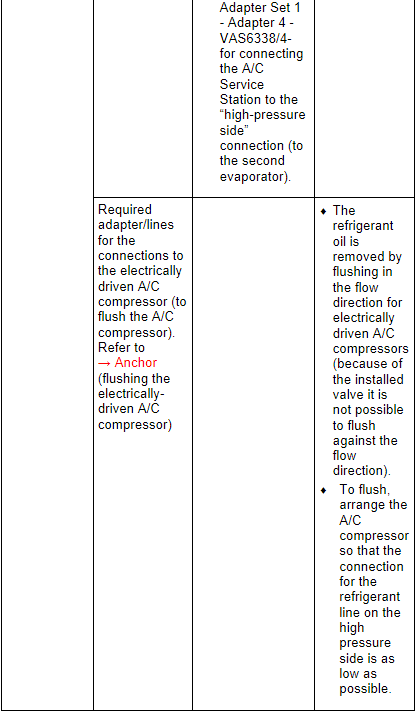
General notes to remove the refrigerant oil from the electrically driven A/C compressor (by flushing).
Note
- Electrically driven A/C compressors cannot have the refrigerant oil poured out in the same manner as a mechanically driven A/C compressor. There is no drain plug and because it is installed inside defending on the version only a specialized part or no refrigerant oil can be poured out. Depending on the version and the storage of the A/C compressor there remains when pouring our approximately 30 to 80 cm 3 refrigerant oil in the A/C compressor (the electrically driven A/C compressor cannot be turned). For this reason, the A/C compressor is to be flushed to remove the refrigerant oil and to determine the amount of refrigerant oil in the A/C compressor, depending on the complaint. Refer to → Chapter "Compressor, Replacing without the Need for Flushing Refrigerant Circuit".
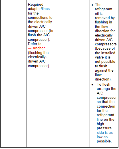
- The refrigerant oil can be removed by flushing in the flow direction for electrically driven A/C compressors (because of the installed valve it is not possible to flush against the flow direction).
- To flush, arrange the A/C compressor so that the connection for the refrigerant line on the high pressure side is as low as possible.
- The electrically driven A/C compressor is to be flushed when, there is dirt, too much refrigerant oil is in the refrigerant circuit, or is contaminated (with moisture debris) and to remove refrigerant oil from the A/C compressor. In these cases the refrigerant circuit must also be flushed, so that it will be cleaned and the correct refrigerant oil quantity for the refrigerant circuit can be set. Refer to → Chapter "Refrigerant Oil Capacities".
- If the electrically driven A/C compressor is replaced, it is not always necessary to flush the coolant circuit. The amount of refrigerant oil found in the removed A/C compressor can be removed by flushing the A/C compressor. Pour the refrigerant oil out of the new A/C compressor so that only the amount remains (plus 10 cm 3) as before the old A/C compressor was flushed out. Refer to → Chapter "Compressor, Replacing without the Need for Flushing Refrigerant Circuit".
- To remove the refrigerant oil from the removed A/C compressor the refrigerant oil must be flushed from the replaced A/C compressors and the removed about measured (Empty the used oil collection from the A/C service station before flushing). Pour the refrigerant oil out of the new A/C compressor so that only the amount or refrigerant oil remains (plus 10 cm 3) in the new A/C compressor as the amount of flushed out refrigerant oil from the old A/C compressor. Dispose of the refrigerant oil removed from the defective and the new A/C compressor and poured out refrigerant oil from the new A/C compressor.
- In not enough refrigerant oil can be poured out from the A/C compressor to be installed, flush the new A/C compressor. Fill the A/C compressor to be installed in after flushing with as much new refrigerant oil as was flushed from the removed A/C compressor. Example: from the removed A/C compressor 120 cm 3 refrigerant oil removed in the new A/C compressor to be installed there are 200 cm 3. Refer to the data plate and → Chapter "Refrigerant Oil Capacities". Then from the A/C compressor to be installed 110 cm 3 (120 cm 3 minus 10 cm 3) must be poured out so that the refrigerant oil quantity in the refrigerant circuit after installing is correct. If the required amount of refrigerant oil cannot be poured out, flush the A/C compressor to be installed. In the new A/C compressor as much refrigerant oil is to be filled as was flushed out of the old A/C compressor.
Flush the Electrically Driven A/C Compressor
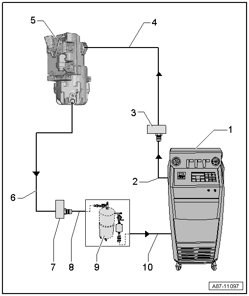
1 - A/C Service Station
- With electronics and a flushing program, A/C Service Station With Flushing Device. Refer to the Parts Catalog (Tools; Special Tools and Equipment: A/C and Heating).
- If an A/C service station without a flushing program is used, the procedure must be performed manually (evacuate, flush three times with at least 2 kg refrigerant each and extract refrigerant again, evacuate).
2 - A/C Service Station Refrigerant Hose
- From high pressure side of A/C service station (mostly colored red) to low pressure side connection of A/C compressor on refrigerant circuit (larger diameter).
3 - Adapter to the Connection for the Low Pressure Side on the A/C Compressor
- There are different versions depending on vehicle. Refer to → Chapter "Adapter for Assembling Flushing Circuit".
- Use the adapter from the Refrigerant Circuits Adapter Set 1 -VAS6338/1- (here the Refrigerant Circuits Adapter Set 2 - Adapter 41 -VAS6338/41-).
4 - Refrigerant Line
- To the A/C compressor connection on the adapter. Refer to -item 3-
Note
- Only use the refrigerant line when the Refrigerant Circuits Adapter Set 2 - Adapter 41 -VAS6338/41- is not available.
- If the Refrigerant Circuits Adapter Set 2 - Adapter 41 -VAS6338/41- is not available to remove the flushing circuit, for example remove the refrigerant lines to the condenser, from the vehicle (or use a refrigerant line with the part number 7L6 820 744 AD). Refer to the Parts Catalog).
5 - Electrically-Driven A/C Compressor
- The A/C compressor is flushed in the flow direction (from the low pressure side input to the high pressure side output)
- So that as much refrigerant oil as possible is flushed out from the A/C compressor, the A/C compressor must be positioned so that the high pressure side output is as low as possible
6 - Refrigerant Line
- To the A/C compressor connection on the adapter. Refer to -item 7-
Note
- Only use the refrigerant line when the Refrigerant Circuits Adapter Set 2 - Adapter 40 -VAS6338/40- is not available.
- If the Refrigerant Circuits Adapter Set 2 - Adapter 40 -VAS6338/40- is not available to remove the flushing circuit use for example on a refrigerant line with the part number 7L6 820 721 BF or 4G0 260 701 AB. Refer to the Parts Catalog.
7 - Adapter to the Connection for the High Pressure Side on the Refrigerant Circuit
- There are different versions depending on vehicle. Refer to → Chapter "Adapter for Assembling Flushing Circuit".
- Use the adapter from the Refrigerant Circuits Adapter Set 1 -VAS6338/1- (here the Refrigerant Circuits Adapter Set 2 - Adapter 40 -VAS6338/40-).
8 - Charge Hose for Refrigerant Circuit Flushing Device
- From connection to the high pressure side of the A/C compressor on the refrigerant circuit (smaller diameter) to input of refrigerant circuit flushing device.
9 - Flushing Equipment for Refrigerant Circuits
- There are different versions of the Refrigerant Circuit Flushing Device. Refer to the Parts Catalog (Tools; Special Tools and Equipment: A/C and Heating).
- With filter, viewing glass, safety valve, heating, refrigerant container etc. (depending on version).
- Depending on the construction of the A/C service station and of refrigerant circuit flushing device, a check-valve may be installed at output of refrigerant circuit flushing device (to guarantee correct direction of refrigerant flow during flushing).
10 - A/C Service Station Refrigerant Hose
- From the low pressure side of the service station (mostly blue) to the output of the flushing device for refrigerant circuits.
Adapter for Assembling Flushing Circuit
- Various adapters which are required to connect the Air Conditioning (A/C) service station to the refrigerant circuit for flushing and to bridge the removed receiver/dryer or reservoir and expansion valve (specific to vehicle) are in the following table.
- Using a charge hose with 5/8 -18 UNF connections (short version, for example Refrigerant Circuits Adapter Set 1 - Adapter 31 -VAS6338/31-), connect the two adapters (contained in Refrigerant Circuits Adapter Set 1 -VAS6338/1-) which have been installed for the removed reservoir or receiver/dryer.
- If a flushed refrigerant circuit is not reassembled immediately after flushing, adapters remain at connections and seal the connections at the adapters using Refrigerant Circuits Adapter Set 1 - Adapter 30 -VAS6338/30- (from Refrigerant Circuits Adapter Set 1 -VAS6338/1-).
- Depending on the version of the compressor and time period of production, different connection and sealing techniques can be found for the refrigerant circuit. Refer to → Heating, Ventilation and Air Conditioning; Rep. Gr.87; System Overview - Refrigerant Circuit (vehicle-specific repair manual).
- Beginning from production year 2006, the name of the "Zexel" A/C compressor was changed from "Zexel" to "Valeo".
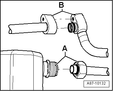
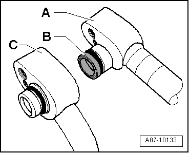
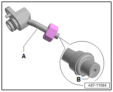
Block or screw connections
- Screw connection -A-
- Block connection -B-
Block connections with different types of seals
- Block connection with radially sealed connection -A- (with plastic or metal guide -B-)
- Block connection with axial sealing connection -C-
Audi A1 and Audi A2
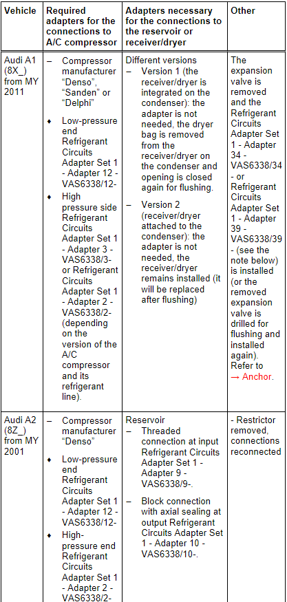
Note
- The receiver/dryer may be attached to or integrated in the condenser on the Audi A1/S1, depending on the version of the condenser. A dryer cartridge is installed in the integrated receiver/dryer and can be replaced separately. After flushing, the attached receiver/dryer (introduction still open) must be replaced after the flushing. Refer to the Parts Catalog and → Heating, Ventilation and Air Conditioning; Rep. Gr.87; System Overview - Refrigerant Circuit (vehicle-specific repair manual).
- There are different versions of the A/C unit (different heater core and sears different expansion valve etc.) depending on time period of production and from the VIN number on Audi A1/S1. Refer to the Parts Catalog. For vehicles with the type key "8X1" and "8XA" in the VIN number an expansion valve is installed, on those where both refrigerant lines are attached above, here the Refrigerant Circuits Adapter Set 1 - Adapter 34 -VAS6338/34- fits. For vehicles with the type key "8XF" and "8XK" in the VIN number an expansion valve is installed, on those where both refrigerant lines are attached below, here the Refrigerant Circuits Adapter Set 1 - Adapter 39 -VAS6338/39- fits. Refer to → Heating, Ventilation and Air Conditioning; Rep. Gr.87; Refrigerant Circuit; Expansion Valve, Removing and Installing (vehicle-specific repair manual).
Audi A3, Audi Q3 and Audi TT
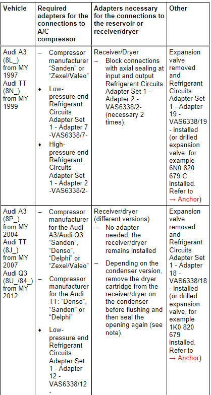
Note
- The version of the receiver/dryer on the Audi A3, Audi Q3 and Audi TT will differ depending on the manufacturer of the condenser. An Audi TT (8J_) from MY 2007 with a 5-cylinder engine has a different condenser version than on models with a 4- or 6-cylinder engine. The receiver/dryer is, for example, inside the condenser. The integrated receiver/dryer has a dryer cartridge that is no longer available as a replacement part. If there are complaints, then it is necessary to replace the complete condenser. Refer to the Parts Catalog and → Heating, Ventilation and Air Conditioning; Rep. Gr.87; System Overview - Refrigerant Circuit (vehicle-specific repair manual).
- If the receiver/dryer or dryer cartridge is integrated in the condenser, then it cannot be replaced separately or is not available as a single part, and the condenser must be replaced. Refer to → Heating, Ventilation and Air Conditioning; Rep. Gr.87; System Overview - Refrigerant Circuit (vehicle-specific repair manual) and the Parts Catalog.
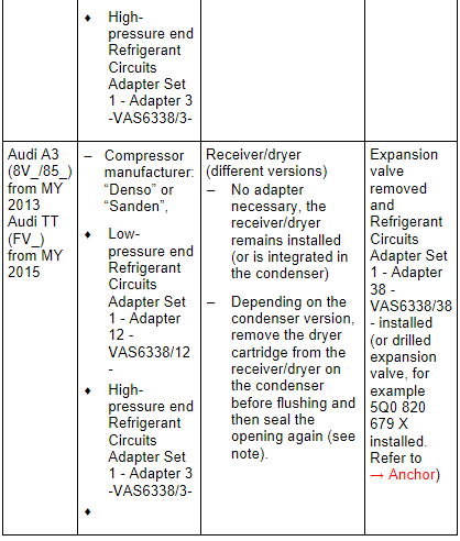
Audi A3 e-tron
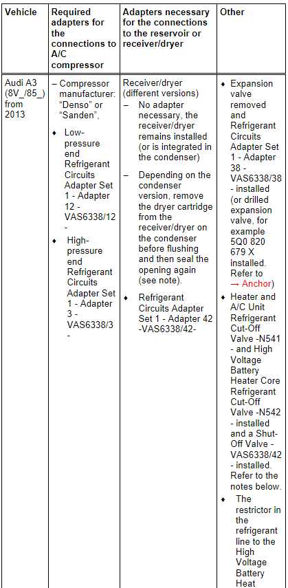
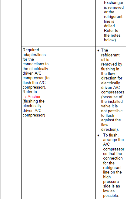
Note
- On the Audi A3 e-tron the refrigerant circuit is flushed in two sections. In the first flushing cycle, the adapter, which is installed for the Heater and A/C Unit Refrigerant Cut-Off Valve -N541-, is opened and the adapter, which is installed for the High Voltage Battery Heater Core Refrigerant Cut-Off Valve -N542- is closed. Thus the refrigerant circuit with the evaporator in the A/C unit is flushed. In the second flushing cycle, the adapter, which is installed for the Heater and A/C Unit Refrigerant Cut-Off Valve -N541-, is closed and the adapter, which is installed for the High Voltage Battery Heater Core Refrigerant Cut-Off Valve -N542- is opened. From this the refrigerant circuit with the evaporator in the high voltage battery heat exchanger is flushed. Refer to → Heating, Ventilation and Air Conditioning; Rep. Gr.87; System Overview - Refrigerant Circuit (vehicle-specific repair manual).
- This illustration shows a refrigerant line -A- with a permanently installed restrictor -B- (without a strainer) This refrigerant line is drilled with a suitable drill 5.0 mm to flush the refrigerant circuit (an inserted restrictor is removed) and cleaned in the flushing circuit before installing. The drilled refrigerant line is replaced after flushing. Refer to the Parts Catalog.
- The diameter of the illustrated variable orifice -B- is approximately 0.7 mm. Depending on the version of the refrigerant line this constriction is either installed fixed in the refrigerant line or only inserted. For the inserted version a strainer for flowing deposits may be installed, which can be blocked by the variable orifice.
- The version of the receiver/dryer on the Audi A3 will differ depending on the manufacturer of the condenser. The receiver/dryer is, for example, inside the condenser. The integrated receiver/dryer has a dryer cartridge that is no longer available as a replacement part. If there are complaints, then it is necessary to replace the complete condenser. Refer to the Parts Catalog and → Heating, Ventilation and Air Conditioning; Rep. Gr.87; System Overview - Refrigerant Circuit (vehicle-specific repair manual).
- If the receiver/dryer or dryer cartridge is integrated in the condenser, then it cannot be replaced separately or is not available as a single part, and the condenser must be replaced. Refer to → Heating, Ventilation and Air Conditioning; Rep. Gr.87; System Overview - Refrigerant Circuit (vehicle-specific repair manual) and the Parts Catalog.
Audi 80, Audi 90, Audi Coupe, Audi Cabriolet and Audi A4
.png)
.png)
.png)
.png)
Note
- There are different versions of the receiver/dryer on the Audi A4 (8K_) from MY 2008, depending on the condenser manufacturer. Refer to → Heating, Ventilation and Air Conditioning; Rep. Gr.87; System Overview - Refrigerant Circuit (vehicle-specific repair manual). The receiver/dryer may be attached to or integrated in the condenser, depending on the version of the condenser. The integrated receiver/dryer has a dryer cartridge that is no longer available as a replacement part. In the event there is a complaint on a vehicle with this condenser, the condenser must be completely replaced. Refer to the Parts Catalog.
- If the receiver/dryer or dryer cartridge is integrated in the condenser, then it cannot be replaced separately or is not available as a single part, and the condenser must be replaced. Refer to → Heating, Ventilation and Air Conditioning; Rep. Gr.87; System Overview - Refrigerant Circuit (vehicle-specific repair manual) and the Parts Catalog.
Audi A5 Coupe and Sportback, Audi Q5, Audi A5 Cabriolet
.png)
Note
- There are different versions of the receiver/dryer on this vehicle, depending on the condenser manufacturer. Refer to → Heating, Ventilation and Air Conditioning; Rep. Gr.87; System Overview - Refrigerant Circuit (vehicle-specific repair manual). The receiver/dryer may be attached to or integrated in the condenser, depending on the version of the condenser. The integrated receiver/dryer has a dryer cartridge that is no longer available as a replacement part. In the event there is a complaint on a vehicle with this condenser, the condenser must be completely replaced. Refer to the Parts Catalog.
- If the receiver/dryer or dryer cartridge is integrated in the condenser, then it cannot be replaced separately or is not available as a single part, and the condenser must be replaced. Refer to → Heating, Ventilation and Air Conditioning; Rep. Gr.87; System Overview - Refrigerant Circuit (vehicle-specific repair manual) and the Parts Catalog.
Audi Q5 Hybrid
.png)
.png)
.png)
Note
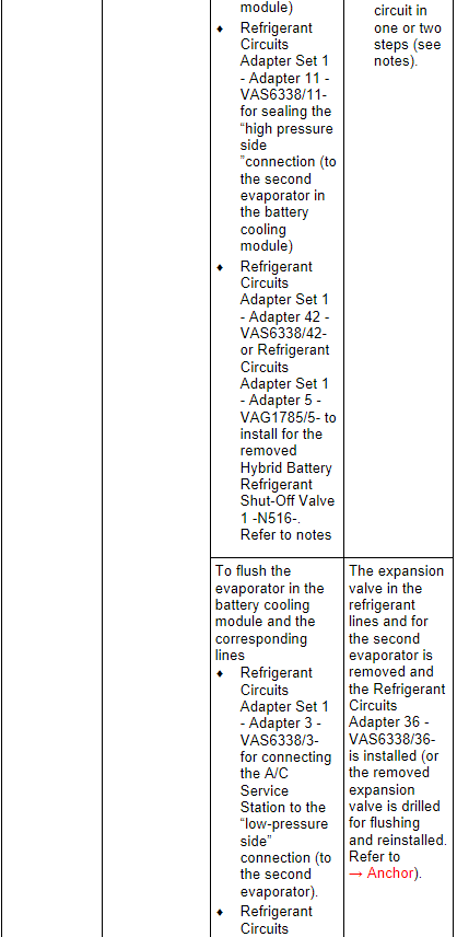
- In vehicles with two evaporators, the refrigerant circuit is flushed in two/three work steps.
- Currently the expansion valves on the evaporator in the A/C unit and on the evaporator in the battery cooling module have the same connections (only the control characteristics and those on the Hybrid Battery Refrigerant Shut-Off Valve 2 -N517- are different).
- The refrigerant circuit cannot be rinsed with a Hybrid Battery Refrigerant Shut-Off Valve 1 -N516- installed in the circuit to the evaporator in the A/C unit. The Hybrid Battery Refrigerant Shut-Off Valve 1 -N516- is in a constricted location and prevents the refrigerant from reaching a sufficient flow speed. If a Shut-Off Valve -VAS6338/42- is available, install it for the Hybrid Battery Refrigerant Shut-Off Valve 1 -N516- and open. If the Shut-Off Valves -VAS6338/42- are not available, but there are two A/C Adapter Set - Adapters 5 -VAG1785/5- the circuit with the evaporator in the A/C unit can be rinsed in one work procedure (reassemble the circuit with a filler hose and two A/C Adapter Set - Adapters 5 -VAG1785/5-). If the Shut-Off Valves -VAS6338/42- is not available and there is only one A/C Adapter Set - Adapters 5 -VAG1785/5- available, the circuit must be flushed in two steps. From the low pressure connection on the A/C compressor via the evaporator in the A/C unit up to the connection for the removed Hybrid Battery Refrigerant Shut-Off Valve 1 -N516- and from the connection for the removed Hybrid Battery Refrigerant Shut-Off Valve 1 -N516- via the condenser to the high pressure connection on the A/C compressor.
- There are different versions of the receiver/dryer on this vehicle, depending on the condenser manufacturer. Refer to → Heating, Ventilation and Air Conditioning; Rep. Gr.87; System Overview - Refrigerant Circuit (vehicle-specific repair manual). The receiver/dryer may be attached to or integrated in the condenser, depending on the version of the condenser. The integrated receiver/dryer has a dryer cartridge that is no longer available as a replacement part. In the event there is a complaint on a vehicle with this condenser, the condenser must be completely replaced. Refer to the Parts Catalog.
- If the receiver/dryer or dryer cartridge is integrated in the condenser, then it cannot be replaced separately or is not available as a single part, and the condenser must be replaced. Refer to → Heating, Ventilation and Air Conditioning; Rep. Gr.87; System Overview - Refrigerant Circuit (vehicle-specific repair manual) and the Parts Catalog.
Audi 100, Audi A6 (4A_, 4B_ and 4F_), Audi allroad and Audi V8
.png)
.png)
Note
The specifications for the Audi A6 (4F_) from MY 2005 also apply to the Audi S6 and Audi RS 6.
Audi A6 (4G_ or 4X_ for China), Audi A7 (4G_ or 4X_ for China)
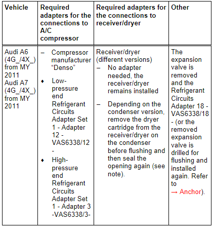
Note
- The type designation 4X_ is used instead of the type designation 4G_ for specific versions in China
- There are different versions of the receiver/dryer on this vehicle, depending on the condenser manufacturer. Refer to → Heating, Ventilation and Air Conditioning; Rep. Gr.87; System Overview - Refrigerant Circuit (vehicle-specific repair manual) and the Parts Catalog.
- If the receiver/dryer or dryer cartridge is integrated in the condenser, then it cannot be replaced separately or is not available as a single part, and the condenser must be replaced. Refer to → Heating, Ventilation and Air Conditioning; Rep. Gr.87; System Overview - Refrigerant Circuit (vehicle-specific repair manual) and the Parts Catalog.
Audi A6 Hybrid
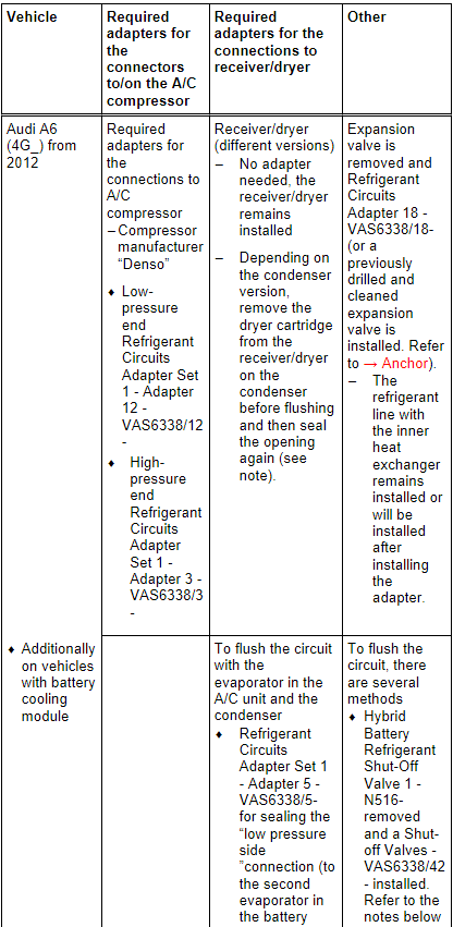
Note
- The type designation 4X_ is used instead of the type designation 4G_ for specific versions in China
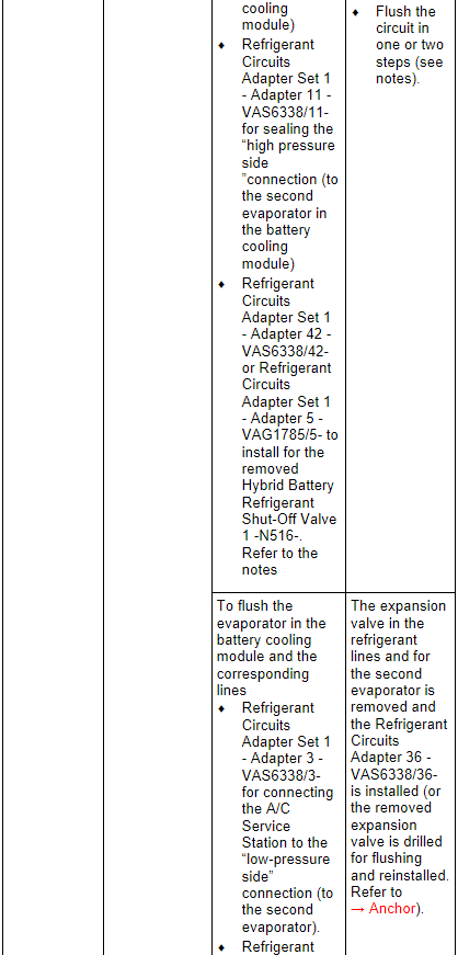
- In vehicles with two evaporators, the refrigerant circuit is flushed in two/three work steps.
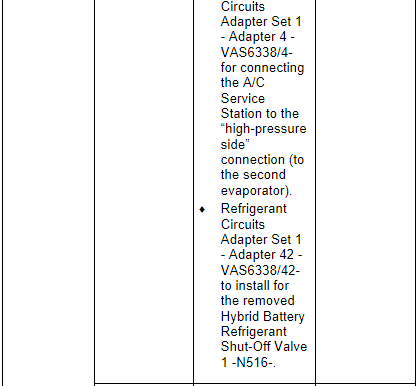
- Currently the expansion valve on the evaporator in the A/C unit and on the evaporator in the battery cooling module have the same connections (only the control characteristics and those on the Hybrid Battery Refrigerant Shut-Off Valve 2 -N517- are different).
- The refrigerant circuit cannot be rinsed with a Hybrid Battery Refrigerant Shut-Off Valve 1 -N516- installed in the circuit to the evaporator in the A/C unit. The Hybrid Battery Refrigerant Shut-Off Valve 1 -N516- is in a constricted location and prevents the refrigerant from reaching a sufficient flow speed. If a Shut-Off Valve -VAS6338/42- is available, install it for the Hybrid Battery Refrigerant Shut-Off Valve 1 -N516- and open. If the Shut-Off Valves -VAS6338/42- are not available, but there are two A/C Adapter Set - Adapters 5 -VAG1785/5- the circuit with the evaporator in the A/C unit can be rinsed in one work procedure (reassemble the circuit with a filler hose and two A/C Adapter Set - Adapters 5 -VAG1785/5-). If the Shut-Off Valves -VAS6338/42- is not available and there is only one A/C Adapter Set - Adapters 5 -VAG1785/5- available, the circuit must be flushed in two steps. From the low pressure connection on the A/C compressor via the evaporator in the A/C unit up to the connection for the removed Hybrid Battery Refrigerant Shut-Off Valve 1 -N516- and from the connection for the removed Hybrid Battery Refrigerant Shut-Off Valve 1 -N516- via the condenser to the high pressure connection on the A/C compressor.
- There are different versions of the receiver/dryer on this vehicle, depending on the condenser manufacturer. Refer to → Heating, Ventilation and Air Conditioning; Rep. Gr.87; System Overview - Refrigerant Circuit (vehicle-specific repair manual). The receiver/dryer may be attached to or integrated in the condenser, depending on the version of the condenser. The integrated receiver/dryer has a dryer cartridge that is no longer available as a replacement part. In the event there is a complaint on a vehicle with this condenser, the condenser must be completely replaced. Refer to the Parts Catalog.
- If the receiver/dryer or dryer cartridge is integrated in the condenser, then it cannot be replaced separately or is not available as a single part, and the condenser must be replaced. Refer to → Heating, Ventilation and Air Conditioning; Rep. Gr.87; System Overview - Refrigerant Circuit (vehicle-specific repair manual) and the Parts Catalog.
- On the Audi A6 hybrid it can be helpful to remove both refrigerant lines in the engine compartment from the inner heat exchanger to flush the components in the battery cooling module and the related refrigerant lines. Then the necessary adapter and related refrigerant hoses can be installed and remove more easily. Refer to → Heating, Ventilation and Air Conditioning; Rep. Gr.87; Refrigerant Circuit; System Overview - Refrigerant Circuit.
- If on the Audi A6 hybrid the knurled nut of the filler hose on the refrigerant line to the evaporator in the battery cooling module installed Refrigerant Circuits Adapter Set 1 - Adapter 3 -VAS6338/3- cannot be installed on the connection (depending of the tolerance on the separation of the refrigerant pipe on the connection) the refrigerant pipe can be carefully bent approximately 1 mm to the side.
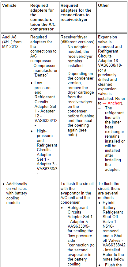
Audi A8
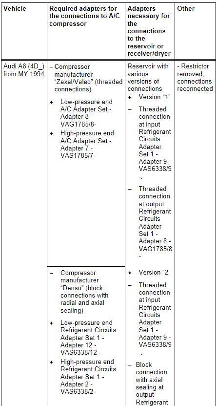
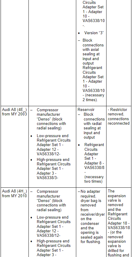
Note
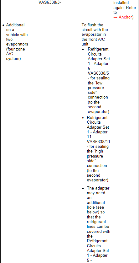
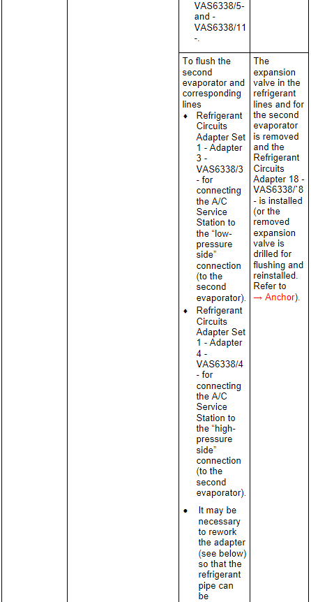
- In vehicles with two evaporators, the refrigerant circuit is flushed in two work steps.
- Currently the front and rear expansion valves have the same connections (only the control characteristics are different)
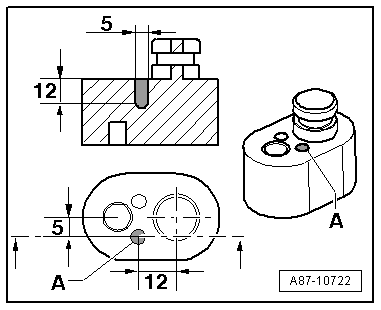
Drill an additional hole in the Refrigerant Circuits Adapter Set 1 - Adapter 5 -VAS6338/5- and -VAS6338/11-.
- Drill a hole -A- in addition to the already existing hole (the dimensions in the illustration are given in mm).
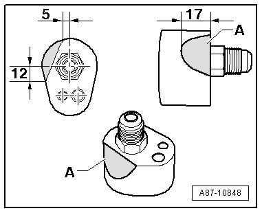
Rework the Refrigerant Circuits Adapter Set 1 - Adapter 3 -VAS6338/3-
- Sand off or file off the Refrigerant Circuits Adapter Set 1 - Adapter 3 -VAS6338/3- near -A- without bending the refrigerant pipe (dimensions are in mm).
Note
- In vehicles with two evaporators, the refrigerant circuit is flushed in two/three work steps.
- Currently the expansion valve on the evaporator in the A/C unit and on the evaporator in the battery cooling module do not have the same connections.
- The refrigerant circuit cannot be rinsed with a Hybrid Battery Refrigerant Shut-Off Valve 1 -N516- installed in the circuit to the evaporator in the A/C unit. The Hybrid Battery Refrigerant Shut-Off Valve 1 -N516- is in a constricted location and prevents the refrigerant from reaching a sufficient flow speed. If a Shut-Off Valve -VAS6338/42- is available, install and open it for the Hybrid Battery Refrigerant Shut-Off Valve 1 -N516-. If the Shut-Off Valve -VAS6338/42- is not available, but there are two A/C Adapter Set - Adapters 5 -VAG1785/5- and the circuit with the evaporator in the A/C unit can be rinsed in one work procedure (reassemble the circuit with a filler hose and two A/C Adapter Set - Adapters 5 -VAG1785/5-). If the Shut-Off Valves -VAS6338/42- is not available and there is only one A/C Adapter Set - Adapters 5 -VAG1785/5- available, the circuit must be flushed in two steps. From the low pressure connection on the A/C compressor via the evaporator in the A/C unit up to the connection for the removed Hybrid Battery Refrigerant Shut-Off Valve 1 -N516- and from the connection for the removed Hybrid Battery Refrigerant Shut-Off Valve 1 -N516- via the condenser to the high pressure connection on the A/C compressor.
- There are different versions of the receiver/dryer on this vehicle, depending on the condenser manufacturer. Refer to → Heating, Ventilation and Air Conditioning; Rep. Gr.87; System Overview - Refrigerant Circuit (vehicle-specific repair manual). The receiver/dryer may be attached to or integrated in the condenser, depending on the version of the condenser. The integrated receiver/dryer has a dryer cartridge that is no longer available as a replacement part. In the event there is a complaint on a vehicle with this condenser, the condenser must be completely replaced. Refer to the Parts Catalog.
- If the receiver/dryer or dryer cartridge is integrated in the condenser, then it cannot be replaced separately or is not available as a single part, and the condenser must be replaced. Refer to → Heating, Ventilation and Air Conditioning; Rep. Gr.87; System Overview - Refrigerant Circuit (vehicle-specific repair manual) and the Parts Catalog.
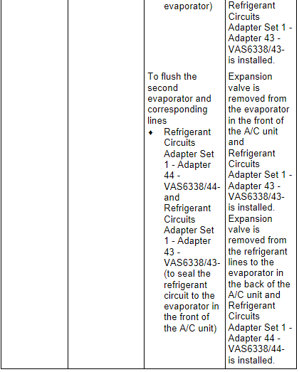
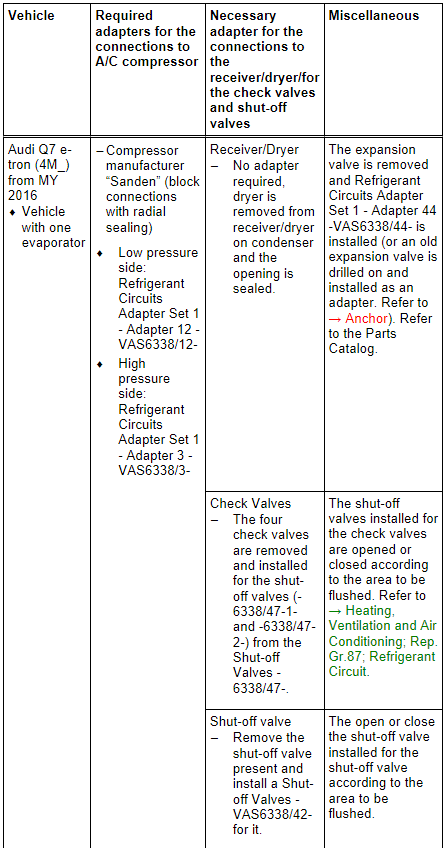
Audi Q7, Audi Q7 e-tron
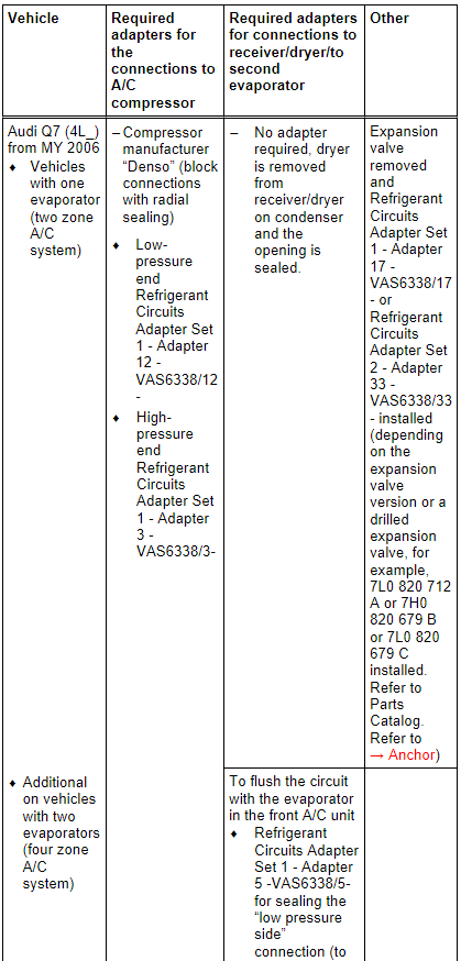
Note
In vehicles with two evaporators, the refrigerant circuit is flushed in two work steps.
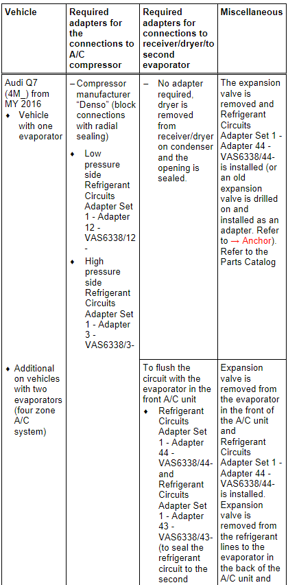
Note
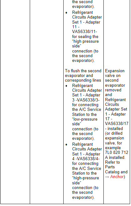
- In vehicles with two evaporators, the refrigerant circuit is flushed in two work steps.
- On vehicles with two evaporators, the refrigerant circuit with the evaporator in the front of the A/C unit is flushed first. So that the refrigerant flows in a fixed direction when flushing, the refrigerant circuit to the second evaporator (in rear of A/C unit) must be blocked off. This is done by removing the expansion valve in the refrigerant lines to the second evaporator and installing the Refrigerant Circuits Adapter Set 1 - Adapter 43 -VAS6338/43- (closed adapter). After the refrigerant circuit with the evaporator is flushed, switch both adapters Refrigerant Circuits Adapter Set 1 - Adapter 43 - VAS6338/43- and Refrigerant Circuits Adapter Set 1 - Adapter 44 - VAS6338/44- and flush the refrigerant circuit with the evaporator in the rear of the A/C unit.
Note
- On the Audi Q7 e-tron the refrigerant circuit is flushed in four steps (flushing circuit). Refer to → Heating, Ventilation and Air Conditioning; Rep. Gr.87; Refrigerant Circuit (Cleaning the A/C system refrigerant circuit).
- So that the entire refrigerant circuit can be flushed, on the Audi Q7 e-tron not only the installed shut-off valve must be positioned correctly (opened or closed). Additionally the electrically activated valves (in the valve block) must be positioned correctly. The activation of the electric valves takes place via different routines which are stored in the respective control module (for example in the Thermal Management Control Module -J1024-). Refer to → Heating, Ventilation and Air Conditioning; Rep. Gr.87; Refrigerant Circuit (Cleaning the A/C system refrigerant circuit).
- To flush on the Audi Q7 e-tron the refrigerant circuit is divided into multiple sections and then cleaned respectively in a flushing cycle. The division takes place by activating the installed electrically activated valves and via the installed manually activated hand shut-off valves. Refer to → Heating, Ventilation and Air Conditioning; Rep. Gr.87; Refrigerant Circuit (Cleaning the A/C system refrigerant circuit) use the Vehicle Diagnostic Tester in the "Guided Fault Finding" function.
- The design of the different flushing circuits for the Q7 e-tron is described in the respective vehicle-specific repair manual. Refer to → Heating, Ventilation and Air Conditioning; Rep. Gr.87; Refrigerant Circuit (Cleaning the A/C system refrigerant circuit).
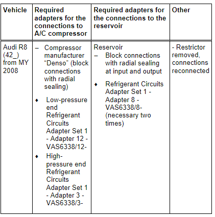
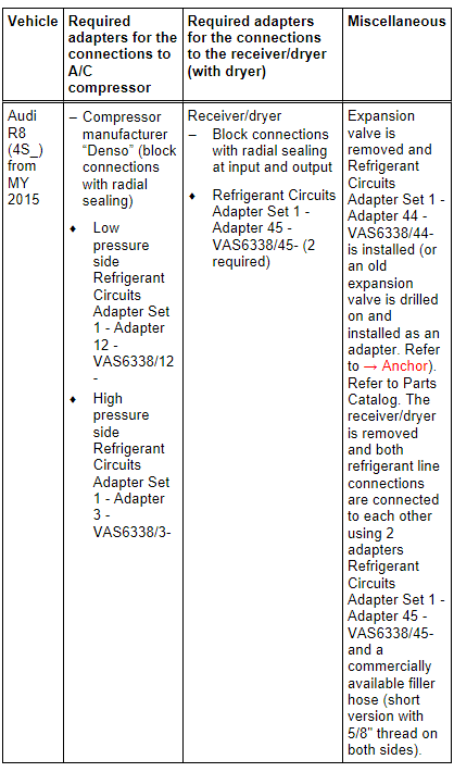
Audi R8
Note
- The A/C compressor can only be removed when the engine is removed on the Audi R8. The refrigerant lines must be removed in order to be able to flush the refrigerant circuit. Refer to → Heating, Ventilation and Air Conditioning; Rep. Gr.87 ; System Overview - Refrigerant Circuit (vehicle-specific repair manual). With the A/C compressor installed the refrigerant oil quantity in the A/C compressor cannot be emptied, For this reason flushing the refrigerant circuit with the A/C compressor installed would not be productive.
- Both installed condensers are flushed in opposite direction of the refrigerant flow direction.
Note
- Depending on the engine, the A/C compressor can only be removed when the engine is removed on the Audi R8. The refrigerant lines must be removed in order to be able to flush the refrigerant circuit. Refer to → Heating, Ventilation and Air Conditioning; Rep. Gr.87 ; System Overview - Refrigerant Circuit (vehicle-specific repair manual). With the A/C compressor installed the refrigerant oil quantity in the A/C compressor cannot be emptied, For this reason flushing the refrigerant circuit with the A/C compressor installed would not be productive.
- Both installed condensers are flushed in opposite direction of the refrigerant flow direction.
- A short version of the filler hose is also included in the Refrigerant Circuits Adapter Set 1 -VAS6338/1-.
- The receiver/dryer could potentially be flushed but it will take too much refrigerant because of its large internal volume; the receiver/dryer would ice-up too much when extracting the refrigerant, the refrigerant would evaporate too slowly and extraction would be prolonged too much.
