Audi A6 Typ 4G: Identification
PR Number Allocation - Brakes
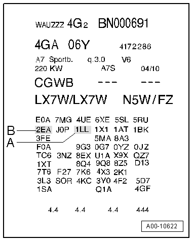
The brake system installed in a vehicle is documented on the vehicle data sticker via the relevant PR number.
Example of a vehicle data label:
A - Front Brakes 1LL
B - Rear Brakes 2EA
- Allocation. Refer to the Parts Catalog.
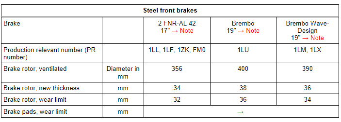
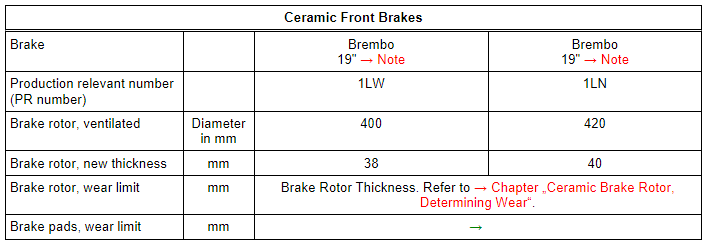
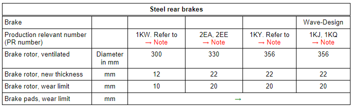
- The tables explain the PR numbers. These are important for the brake caliper/brake rotor and brake pad combination. Refer to → Chapter "Technical Data, Brakes".
Safety Precautions
Safety Precautions when Working on Vehicles with Start/Stop System
Note the following when working on vehicles with a Stop/Start system:
 WARNING
There is a risk of injury if the engine starts automatically on vehicles with a Start/Stop System.
- For vehicles with an activated Start/Stop System (recognizable by a message in the instrument cluster), the engine may start automatically as needed.
- Make sure that the Start/Stop System is deactivated when working on the vehicle (turn off the ignition, turn on the ignition when necessary).
Safety Precautions during Road Test with Testing Equipment
Note the following if testing equipment must be used during a road test:
WARNING
Distractions and testing equipment that is not secured properly increases the risk of an accident.
There is a risk of the front passenger airbag deploying during an accident.
- Operating testing equipment while driving causes distractions.
- There is an increased risk of personal injury if testing equipment is not secured properly.
Always secure testing equipment on the rear seat with a strap and have a second person operate them from the rear seat.
Repair Information
Guidelines for Clean Working Conditions
- The highest level of cleanliness is required when working on the ABS. Using any products which contain mineral oil such as oils, greases etc. is strictly prohibited.
- Thoroughly clean all connection points and their surrounding areas before loosening. However, do not use aggressive cleaning agents such as brake cleaner, gasoline, thinners or similar compounds.
- Place the removed parts on a clean surface and cover them.
- Carefully cover or seal opened components if repairs are not performed immediately (use plugs from Assembly Part Set -5Q0698311-).
- Only use lint-free cloths.
- Remove the replacement parts from their packaging just prior to installing them.
- Only use parts in their original packaging.
- If the system is open, do not work with compressed air and do not move the vehicle.
- Make sure that brake fluid cannot get into the connectors.
General Repair Information
- Hairline cracks on the brake rotor friction surface are often noticed during brake repairs. Hairline cracks up to 10 mm long are not a technical flaw and do not justify a brake rotor replacement.
- Brake rotors and brake pads that have a worn through friction surface should be replaced.
Contact Corrosion
Contact corrosion can occur if incorrect fasteners (bolts, nuts, washers, etc.) are used.
For this reason, only fasteners with a special surface coating are installed.
In addition, rubber or plastic parts and adhesive are made of materials that do not conduct electricity.
If there are doubts about whether the parts are suitable, then use new parts. Refer to the Parts Catalog.
Note:
- Only original replacement parts are recommended. They are checked and compatible with aluminum.
- The use of Audi accessories is recommended.
- Contact corrosion damage is not covered under warranty.
Technical Data
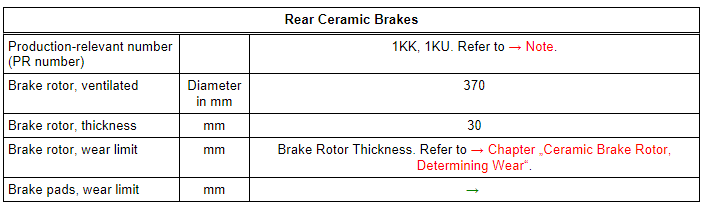
Technical Data, Brakes
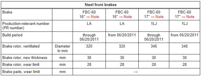
1) Allocation. Refer to the Parts Catalog.
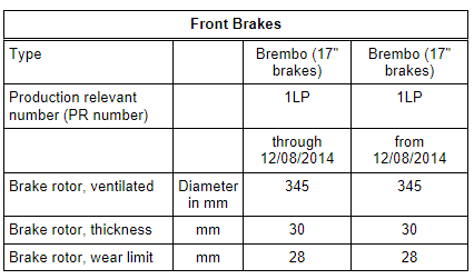
2) Allocation. Refer to the Parts Catalog.
3) Allocation. Refer to the Parts Catalog.
4) Allocation. Refer to the Parts Catalog.