Audi A6 Typ 4G: Transmission Control
Component Location Overview - Transmission Control
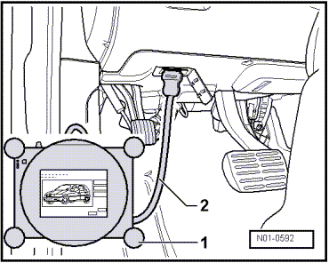
Diagnostic Connection
Installed location: the diagnostic connection for the Vehicle Diagnostic Tester in inside the footwell on the driver side.
All Wheel Drive Control Module -J492- in the A4 Sedan, A5 Coupe and the A5 Cabriolet
Component location: The All Wheel Drive Control Module -J492--A- is located in the spare wheel well in front of the battery.
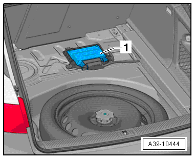
All Wheel Drive Control Module -J492- in the A4 Avant
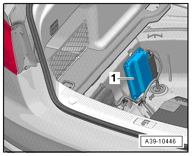
Component location: The All Wheel Drive Control Module -J492--1- is in the luggage compartment on the right in front of the spare wheel well.
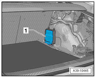
All Wheel Drive Control Module -J492- in the A5 Sportback
Installed location: The All Wheel Drive Control Module -J492--1- is in the rear right wheel housing under the luggage compartment side trim. Refer to → Body Interior; Rep. Gr.70; Luggage Compartment Trim.
All Wheel Drive Control Module -J492- in the Audi A6/A7
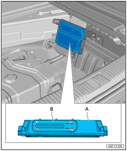
Component location: The All Wheel Drive Control Module -J492--A- is located on the right in the spare wheel well.
All Wheel Drive Control Module -J492- in the A8
Component location: The All Wheel Drive Control Module -J492--1- is located on the left in the spare wheel well.
All Wheel Drive Control Module -J492-, Removing and Installing
 Note
Note
- All Wheel Drive Control Module -J492- component location. Refer to → Chapter "Component Location Overview - Transmission Control".
- Removing and installing is on the A4 Sedan.
- The ignition is off.
- Remove the luggage compartment floor covering.
- Remove the covering and the vehicle tools mount.
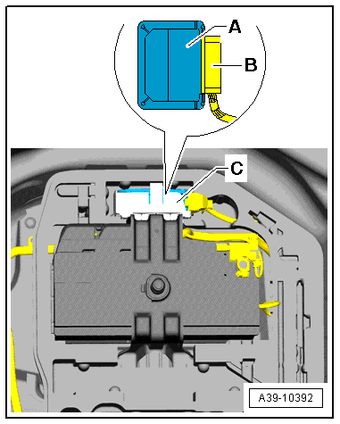
- Remove the All Wheel Drive Control Module -J492--A- from the bracket -C-.
- Disconnect the connector -B- from the All Wheel Drive Control Module -J492-.
- Install the All Wheel Drive Control Module -J492- in reverse order of removal.
- If the All Wheel Drive Control Module -J492- was replaced then additional work is necessary. Refer to → Chapter "All Wheel Drive Control Module -J492-, Additional Work after Replacing".
All Wheel Drive Control Module -J492-, Additional Work after Replacing
Note
Only perform the additional work only if the All Wheel Drive Control Module -J492- was replaced.
- Connect the Vehicle Diagnostic Tester and turn on the ignition.
- Select the function 22 - All Wheel Drive (AWD) Electronics in the vehicle diagnostic tester under Guided Functions in the directory 22- Replacing Control Module.
- Follow all the instructions given by the Vehicle Diagnostic Tester exactly.
With the vehicle diagnostic tester the installed rear final drive is "adapted" on the All Wheel Drive Control Module -J492-.
Note
A system check will take place when the 22 - Control Module, Replacing function is complete. If malfunctions appear, then use "Guided Fault Finding" to correct them.
Special Tools
Special tools and workshop equipment required
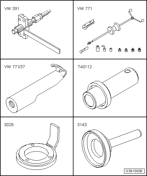
- Puller -VW391-
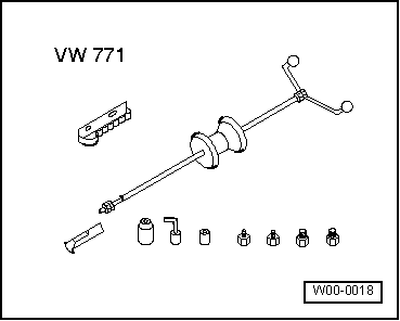
- Slide Hammer-Complete Set -VW771-
- Additional Part for VW771 -VW771/37-
- Thrust Piece -T40112-
- Retainer -3028-
- Seal Driver-Frt Wheel Bearing -3143-
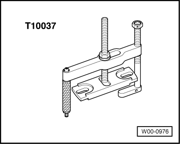
- Puller -T10037-
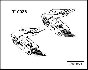
- Tensioning Strap -T10038-
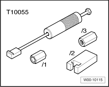
- Puller -T10055-
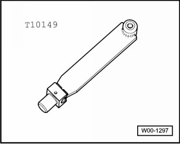
- Wheel Hub Support -T10149-
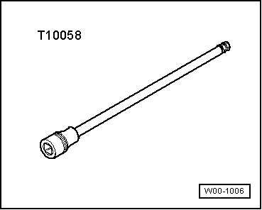
- Hex Ball Socket -T10058-
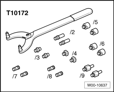
- Counterhold Tool Touareg V10 -T10172-
- Adapter -T10172/5- (M8 Bolts)
- Adapter -T10172/6- (M10 Bolts)
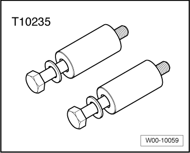
- Adapter -T10235-
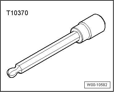
- Socket 4 mm -T10370-
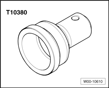
- Thrust Piece -T10380-
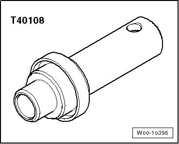
- Thrust Piece -T40108-
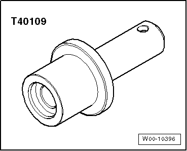
- Thrust Piece -T40109-
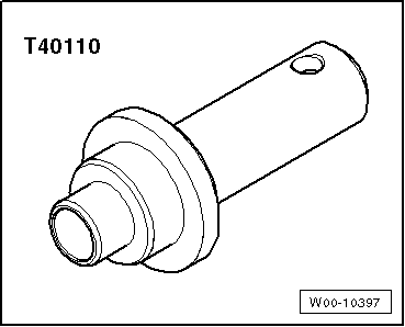
- Thrust Piece -T40110-
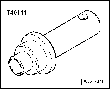
- Thrust Piece -T40111-
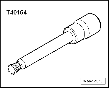
- Socket XZN 12 -T40154-
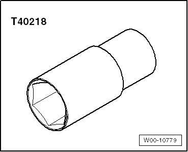
- Socket 27 mm -T40218-
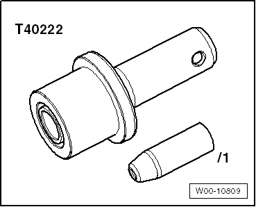
- Assembly Tool -T40222-
- Assembly Tool -T40222/1-
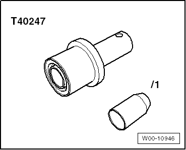
- Assembly Tool -T40247-
- Guide Sleeve -T40247/1-
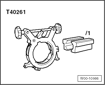
- Flanging Tool -T40261-
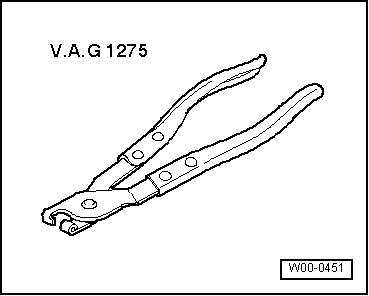
- Hose Clamp Pliers -VAG1275-
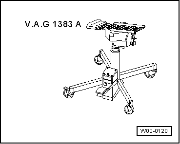
- Engine-Transmission Jack -VAG1383 A- with Universal Transmission Support -VAG359/2-.
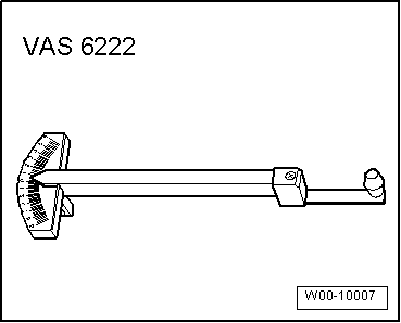
- Friction Gauge -VAS6222-
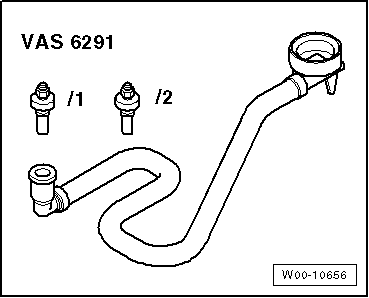
- Charging Device for Haldex Coupling 2 -VAS6291- or Charging Device for Haldex Coupling 2 -VAS6291A-
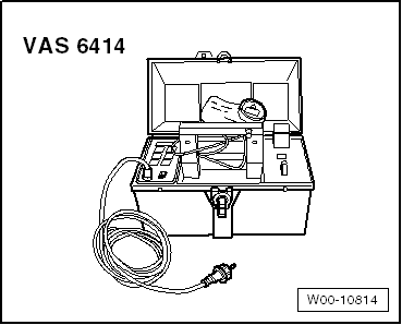
- Inductive Heater -VAS6414-
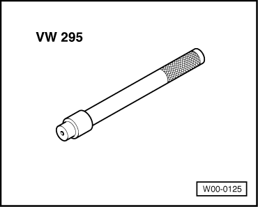
- Needle Bearing Drift -VW295-
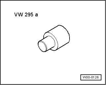
- Needle Bearing Drift -VW295A-
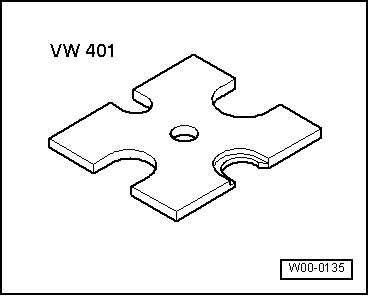
- Thrust Plate -VW401-
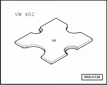
- Thrust Plate -VW402-
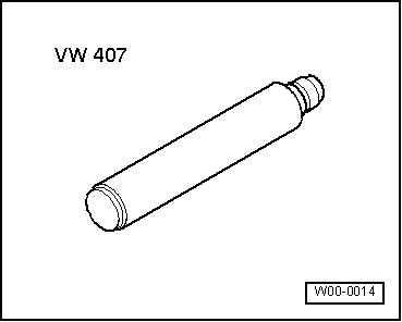
- Punch -VW407-
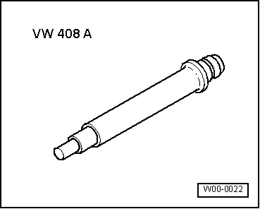
- Punch -VW408A-
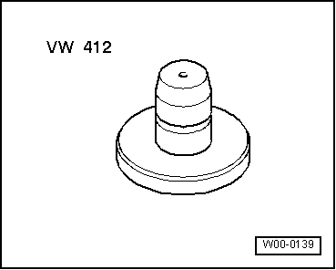
- Punch -VW412-
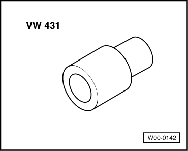
- Thrust Pad 16.5/28 mm Diameter -VW431-
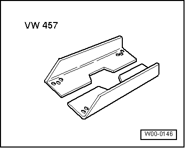
- Support Channels -VW457-
- Slide Hammer-Complete Set -VW771-
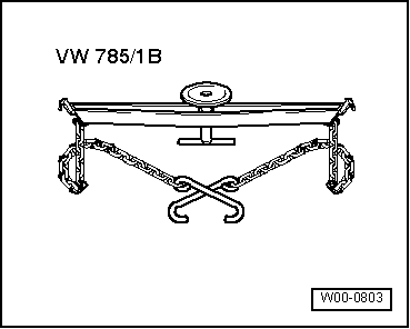
- Transmission Support -VW785/1B-
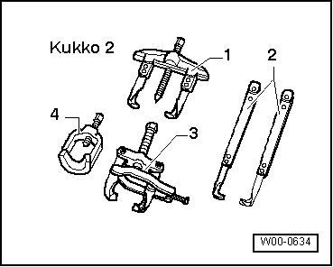
- -3-Separating Tool 22 to 75 mm, for example, Kukko Separating Tool 12-75 mm -17/1-
- -3-Kukko Separating Tool 22-115 mm, for example, Kukko Separating Tool 22-115 mm -17/2-
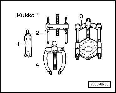
- -1-2-Arm Puller Kukko -20/10-
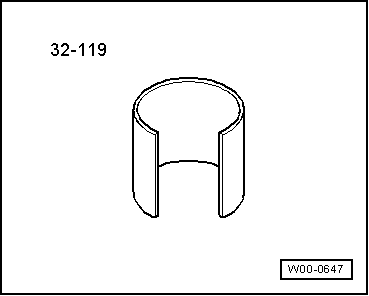
- Sleeve -32 - 119-
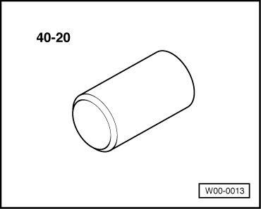
- Sleeve -40 - 20-
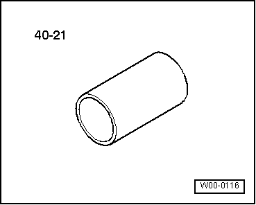
- Sleeve -40 - 21-
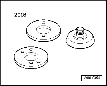
- Seal Press Sleeve -2003/1- from the Seal Installer -2003-
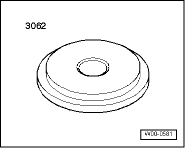
- Thrust Pad -3062-
- Alignment Fixture-4W Dr. Shaft -3139-

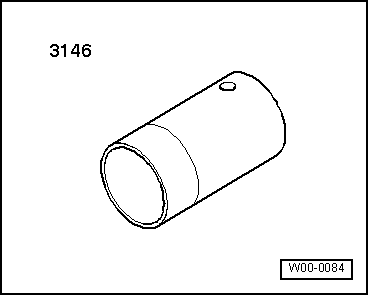
- Press Support-R and R Ball Joints -3146-
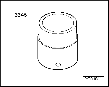
- Press Tube -3345-
- Not illustrated:
- Thrust Piece -T40221-
- Oil Filling Adapter -VAS6291/2- or Oil Filling Adapter -VAS6291/3-
Revision History
DRUCK NUMBER: A005A502721
.png)
