Audi A6 Typ 4G: Front Brake Caliper, Removing and Installing
Brake Caliper, Removing and Installing, Steel Brakes, 1LA/1LJ
Special tools and workshop equipment required
- Torque Wrench 1332 40-200Nm -VAG1332-
 Caution
This procedure contains mandatory replaceable parts. Refer to component overview and parts catalog prior to starting procedure.
Mandatory Replacement Parts
- Bolts - Stub axle carrier to brake carrier
 Note
Note
In the following description the brake caliper is removed with the brake carrier and brake pads. The brake hose remains connected.
Removing
- Remove the affected front wheel. Refer to → Suspension, Wheels, Steering; Rep. Gr.44; Wheels, Tires.
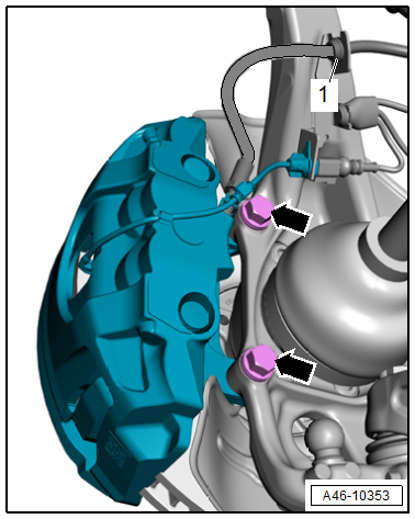
- Free up the wire for the brake pad wear sensor, to do so open the dust cap -2- and disengage the wire from the brake caliper arrows.
- Remove the contact -3- for the brake pad wear sensor from the brake pad, while being careful of the clamps -1-.
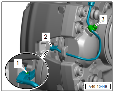
Note
If the clamps -1- go missing, the brake pad wear sensor must be replaced.
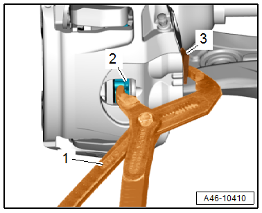
Note
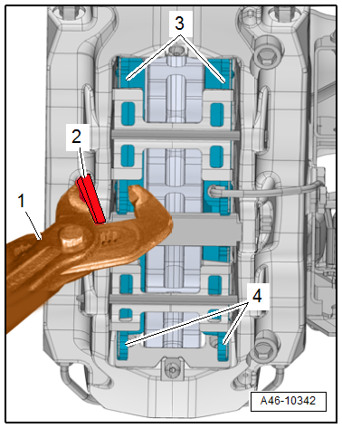
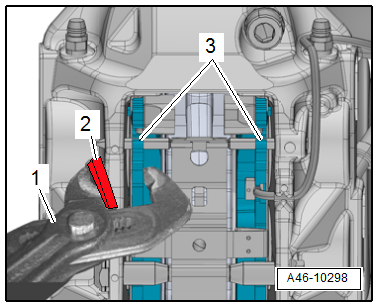
- For easier removal of the brake caliper from the brake rotor, push the brake pad -2- back lightly with pliers -1-, as shown in the illustration.
- To prevent damage to the paint coat on the brake caliper, place a piece of rubber -3- between the pliers and the brake caliper.
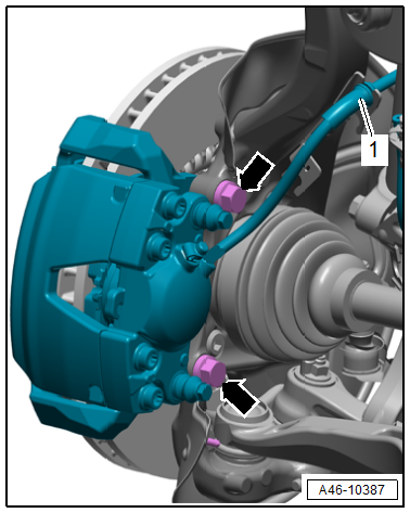
- Free up the brake hose -1- from the bracket.
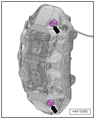
- Remove the bolts -arrows- and carefully pull the brake caliper with the brake carrier and the installed brake pads from the brake rotor.
Caution
There is a risk of damaging the brake hose.
- Do not let the brake caliper hang on the brake hose. Do not support the weight with the brake hose.
- Replace the brake hose if damaged.
There is a risk of damaging the brake caliper piston.
Do not press the brake pedal when the brake caliper is removed.
- Hang the brake caliper with the brake carrier on the body using suitable wire.
Installing
Install in reverse order of removal and note the following:
Note
Replace the brake carrier bolts after removing.
 WARNING
Health Risk.
Do not blow out brake system with compressed air.
Note
Use only mineral spirits to clean the brake caliper.
- Clean the brake caliper.
- Carefully slide the brake caliper with the brake carrier and the installed brake pads over the brake rotor.
- Tighten the new bolts -arrows-.
- Engage the brake hose -1- at the bracket.
- Install the brake pad wear indicator sensor. Refer to → Chapter "Brake Pad Wear Indicator Wire, Removing and Installing, Steel Brakes, 1LA/1LJ".
Note
- Make sure that the connector and brake hose are routed correctly.
- Make sure the brake hose is not blocked, bent, twisted or rubbing against the vehicle.
- Install the front wheel. Refer to → Suspension, Wheels, Steering; Rep. Gr.44; Wheels, Tires.
WARNING
Risk of accident!
- With the vehicle stationary, firmly press the brake pedal several times so that the brake pads in the operating condition properly sit in their respective position.
- Make sure the brakes are working correctly before driving the vehicle for the first time.
Brake Caliper, Removing and Installing, Steel Brakes, 1LF/1LL
Special tools and workshop equipment required
- Torque Wrench 1332 40-200Nm -VAG1332-
Caution
This procedure contains mandatory replaceable parts. Refer to component overview and parts catalog prior to starting procedure.
Mandatory Replacement Parts
- Bolts - Stub axle carrier to brake carrier
Note
In the following description the brake caliper is removed with the brake carrier and brake pads. The brake hose remains connected.
Removing
- Remove the affected front wheel. Refer to → Suspension, Wheels, Steering; Rep. Gr.44; Wheels, Tires.
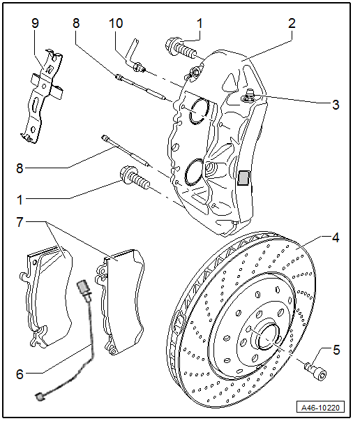
- Remove the contact -1- for the brake pad wear sensor from the brake pad, while being careful of the clips -2-.
- Free up the wire from the brake hose -3- and the bracket -4-.
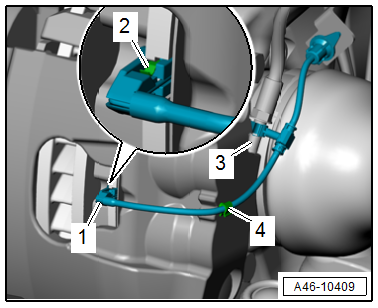
Note
If the clips -2- go missing, the brake pad wear sensor must be replaced.
Note
- For easier removal of the brake caliper from the brake rotor, push the brake pad -2- back lightly with pliers -1-, as shown in the illustration.
- To prevent damage to the paint coat on the brake caliper, place a piece of rubber -3- between the pliers and the brake caliper.
- Free up the brake hose -1- from the bracket.
- Remove the bolts -arrows- and carefully remove the brake caliper with the brake carrier and the installed brake pads from the brake rotor.
Caution
There is a risk of damaging the brake hose.
- Do not let the brake caliper hang on the brake hose. Do not support the weight with the brake hose.
- Replace the brake hose if damaged.
There is a risk of damaging the brake caliper piston.
Do not press the brake pedal when the brake caliper is removed.
- Hang the brake caliper on the body using a suitable wire.
Installing
Install in reverse order of removal and note the following:
Note
Replace the brake carrier bolts after removing.
WARNING
Health Risk.
Do not blow out brake system with compressed air.
Note
Use only mineral spirits to clean the brake caliper.
- Clean the brake caliper.
- Carefully slide the brake caliper with the brake carrier and the installed brake pads over the brake rotor.
- Tighten the new bolts -arrows-.
- Engage the brake hose -1- at the bracket.
- Install the brake pad wear indicator sensor. Refer to → Chapter "Brake Pad Wear Indicator Wire, Removing and Installing, Steel Brakes, 1LF/1LL".
Note
- Make sure that the connector and brake hose are routed correctly.
- Make sure the brake hose is not blocked, bent, twisted or rubbing against the vehicle.
- Install the front wheel. Refer to → Suspension, Wheels, Steering; Rep. Gr.44; Wheels, Tires.
WARNING
Risk of accident!
- With the vehicle stationary, firmly press the brake pedal several times so that the brake pads in the operating condition properly sit in their respective position.
- Make sure the brakes are working correctly before driving the vehicle for the first time.
Brake Caliper, Removing and Installing, 1LP
Special tools and workshop equipment required
- Torque Wrench 1332 40-200Nm -VAG1332-
- Torque Wrench 1332 Insert - Reversible Ratchet -VAG1332/1-
Caution
There is a risk of contamination and paint damage from escaping brake fluid.
- If the brake pads are worn out and brake fluid is filled, the brake fluid may overflow if the pistons in the brake cylinder are pressed back.
- Check the brake fluid level before pressing back the pistons. If there is brake fluid up to the "MAX" mark, some brake fluid will need to be extracted.
- Use the Brake Charger/Bleeder Unit -VAS5234- to extract brake fluid from the brake fluid reservoir.
Removing
- Remove affected front wheel.
- Unclip the brake hose from the bracket pivot bearing
- Unclip the brake pad wear wire.
- Remove the bolts -1-.
Note
Pushing the brake pads slightly back with pliers makes it easier to remove the brake caliper from the brake rotor. To avoid damaging the brake caliper, place a piece of rubber or similar material -2- between the brake caliper. Do not damage the existing brake pad wear indicator cable when doing this.
- Carefully remove the brake caliper with the brake pads still installed.
Note
Do not disassemble the brake caliper. Do not loosen any screws on the brake caliper.
Caution
- Do not let the brake caliper with the brake carrier hang on the brake hose. Do not support the weight with the brake hose.
- Replace the brake hose if damaged.
- Do not press the brake pedal when the brake caliper is removed.
Installing
- Tightening Specifications
Note
- Use new bolts. Refer to Parts Catalog.
- Use only mineral spirits or commercially available brake cleaner to clean the brake caliper.
- Clean brake caliper.
- Carefully press the brake caliper with the brake carrier and the installed brake pads over the brake rotor.
- Tighten the brake caliper with the new bolts.
- Tightening Specifications
- Install the brake hose into the bracket on the pivot bearing.
- Attach the brake pad wear wire.
- Mount the wheels.
- Check brake fluid level, and fill if necessary.
WARNING
Risk of accident!
- With the vehicle stationary, firmly press the brake pedal several times so that the brake pads in the operating condition properly sit in their respective position.
- Make sure the brakes are working correctly before driving the vehicle for the first time.
Brake Caliper, Removing and Installing, Steel Brakes, 1LU
Special tools and workshop equipment required
- Torque Wrench 1332 40-200Nm -VAG1332-
Caution
This procedure contains mandatory replaceable parts. Refer to component overview and parts catalog prior to starting procedure.
Mandatory Replacement Parts
- Bolts - Stub axle carrier to brake carrier
Note
In the following description the brake caliper is removed with the brake carrier and brake pads. The brake hose remains connected.
Removing
Caution
Risk of malfunction.
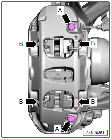
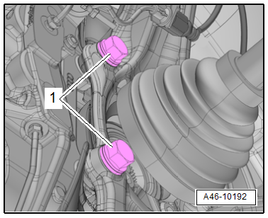
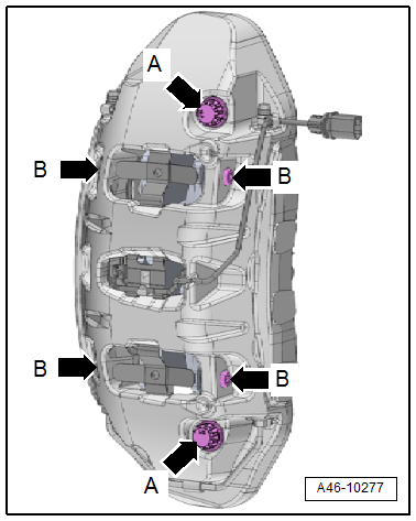
- Do not loosen the bolts -arrows- on the brake caliper.
- Do not remove the guide pins -arrows B-.
Note
The guide pins are only replaced on the ceramic brakes.
- Remove the affected front wheel. Refer to → Suspension, Wheels, Steering; Rep. Gr.44; Wheels, Tires.
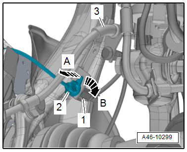
- Disconnect the brake pad wear sensor connector -1-.
- Release the connector -2- to the brake pad wear sensor from its bracket -arrow A- while turning it 90º at the same time -arrow B-.
- Free up the brake hose -3- on the bracket.
Note
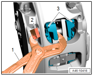
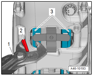
- For easier removal of the brake caliper from the brake rotor, push the brake pads -3-back lightly with pliers -1-.
- To prevent damage to the paint coat on the brake caliper, place a piece of rubber -2- between the pliers and brake caliper.
- Remove the bolts -1- and carefully remove the brake caliper with the brake carrier and the installed brake pads from the brake rotor.
Caution
There is a risk of damaging the brake hose.
- Do not let the brake caliper with the brake carrier hang on the brake hose. Do not support the weight with the brake hose.
- Replace the brake hose if damaged.
There is a risk of damaging the brake caliper piston.
Do not press the brake pedal when the brake caliper is removed.
- Hang the brake caliper on the body using a suitable wire.
Installing
Install in reverse order of removal and note the following:
Note
Replace the brake carrier bolts after removing.
WARNING
Health Risk.
Do not blow out brake system with compressed air.
Note
Use only mineral spirits to clean the brake caliper.
- Clean the brake caliper.
- Slide the brake caliper with the brake pads installed carefully over the brake rotor.
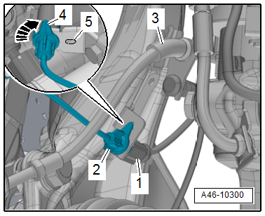
- Tighten the new bolts -1-.
- Secure the brake hose -3- to the bracket.
- Bring the connector -2- into its installed position and turn in the direction of the -arrow- until the tab -4- engages in the opening -5- on the bracket.
- Connect the connector -1-.
Note
- Make sure that the connector and brake hose are routed correctly.
- Make sure the brake hose is not blocked, bent, twisted or rubbing against the vehicle.
- Install the front wheel. Refer to → Suspension, Wheels, Steering; Rep. Gr.44; Wheels, Tires.
WARNING
Risk of accident!
- With the vehicle stationary, firmly press the brake pedal several times so that the brake pads in the operating condition properly sit in their respective position.
- Make sure the brakes are working correctly before driving the vehicle for the first time.
Brake Caliper, Removing and Installing, Steel Brakes, 1LM/1LX
Special tools and workshop equipment required
- Torque Wrench 1332 40-200Nm -VAG1332-
Caution
This procedure contains mandatory replaceable parts. Refer to component overview and parts catalog prior to starting procedure.
Mandatory Replacement Parts
- Bolts - Stub axle carrier to brake carrier
- Bolts - for tension strut
Note
In the following description the brake caliper is removed with the brake pads. The brake hose remains connected.
Removing
Caution
Risk of malfunction.
Do not loosen the bolts -arrows- on the brake caliper.
- Remove the affected front wheel. Refer to → Suspension, Wheels, Steering; Rep. Gr.44; Wheels, Tires.
- Disconnect the brake pad wear sensor connector -1-.
- Release the connector -2- to the brake pad wear sensor from its bracket -arrow A- while turning it 90º at the same time -arrow B-.
- Free up the brake hose -3- on the bracket.
Note
For easier removal of the brake caliper from the brake rotor, push the brake pads -3-back lightly with pliers -1-. To prevent damage to the paint coat on the brake caliper, place a piece of rubber -2- between the pliers and brake caliper.
- Unscrew the bolts -1- and carefully remove the brake caliper with the brake pads from the brake rotor.
Caution
There is a risk of damaging the brake hose.
- Do not let the brake caliper with the brake carrier hang on the brake hose. Do not support the weight with the brake hose.
- Replace the brake hose if damaged.
There is a risk of damaging the brake caliper piston.
Do not press the brake pedal when the brake caliper is removed.
- Hang the brake caliper on the body using a suitable wire.
Installing
Install in reverse order of removal and note the following:
Note
Replace the brake carrier bolts after removing.
WARNING
Health Risk.
Do not blow out brake system with compressed air.
Note
Use only mineral spirits to clean the brake caliper.
- Clean the brake caliper.
- Slide the brake caliper with the brake pads installed carefully over the brake rotor.
- Tighten the new bolts -1-.
- Secure the brake hose -3- to the bracket.
- Bring the connector -2- into its installed position and turn in the direction of the -arrow- until the tab -4- engages in the hole -5- on the bracket.
- Connect the connector -1-.
Note
- Make sure that the connector and brake hose are routed correctly.
- Make sure the brake hose is not blocked, bent, twisted or rubbing against the vehicle.
- Install the front wheel. Refer to → Suspension, Wheels, Steering; Rep. Gr.44; Wheels, Tires.
WARNING
Risk of accident!
- With the vehicle stationary, firmly press the brake pedal several times so that the brake pads in the operating condition properly sit in their respective position.
- Make sure the brakes are working correctly before driving the vehicle for the first time.
Brake Caliper, Removing and Installing, Ceramic Brakes, 1LN/1LW
Special tools and workshop equipment required
- Torque Wrench 1332 40-200Nm -VAG1332-
Caution
This procedure contains mandatory replaceable parts. Refer to component overview and parts catalog prior to starting procedure.
Mandatory Replacement Parts
- Bolts - Stub axle carrier to brake carrier
Note
In the following description the brake caliper is removed with the brake pads. The brake hose remains connected.
Removing
Caution
Risk of malfunction.
- Do not loosen the bolts -arrows- on the brake caliper.
- Replace the guide pins -B arrows- 24 Nm.
- Remove the affected front wheel, while observing the safety precautions for vehicles with ceramic brakes. Refer to → Suspension, Wheels and Steering; Rep. Gr.44; Wheels, Tires.
- Disconnect the brake pad wear sensor connector -1-.
- Release the connector -2- to the brake pad wear sensor from its bracket -arrow A- while turning it 90º at the same time -arrow B-.
- Free up the brake hose -3- on the bracket.
Note
For easier removal of the brake caliper from the brake rotor, push the brake pads -3-back lightly with pliers -1-. To prevent damage to the paint coat on the brake caliper, place a piece of rubber -2- between the pliers and brake caliper.
- Unscrew the bolts -1- and carefully remove the brake caliper with the brake pads from the brake rotor.
Caution
There is a risk of damaging the brake hose.
- Do not let the brake caliper hang on the brake hose. Do not support the weight with the brake hose.
- Replace the brake hose if damaged.
There is a risk of damaging the brake caliper piston.
Do not press the brake pedal when the brake caliper is removed.
- Hang the brake caliper on the body using a suitable wire.
Installing
Install in reverse order of removal and note the following:
Note
Replace the brake caliper bolts after removing.
WARNING
Health Risk.
Do not blow out brake system with compressed air.
Note
Use only mineral spirits to clean the brake caliper.
- Clean the brake caliper.
- Slide the brake caliper with the brake pads installed carefully over the brake rotor.
- Tighten the new bolts -1-.
- Secure the brake hose -3- to the bracket.
- Bring the connector -2- into its installed position and turn in the direction of the -arrow- until the tab -4- engages in the hole -5- on the bracket.
- Connect the connector -1-.
Note
- Make sure that the connector and brake hose are routed correctly.
- Make sure the brake hose is not blocked, bent, twisted or rubbing against the vehicle.
- Install the front wheel, while observing the safety precautions for vehicles with ceramic brakes. Refer to → Suspension, Wheels and Steering; Rep. Gr.44; Wheels, Tires.
WARNING
Risk of accident!
- With the vehicle stationary, firmly press the brake pedal several times so that the brake pads in the operating condition properly sit in their respective position.
- Make sure the brakes are working correctly before driving the vehicle for the first time.
