Audi A6 Typ 4G: Gear Oil
Gear Oil Drain and Inspection Plugs Overview
Gear Oil Drain and Inspection Plugs Overview, 0BE, 0BF
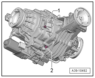
Gear Oil Drain Plug on Rear Final Drive 0BF
1- Check plug for gear oil
- Tightening Specification -item 23-.
- Always replace.
2- Gear oil drain plug
- Tightening Specification -item 17-.
- Always replace.
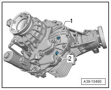
Gear Oil Drain Plug on Rear Final Drive 0BE
1- Check plug for gear oil
- Tightening Specification -item 23-.
- Always replace.
2- Gear oil drain plug
- Tightening Specification -item 17-.
- Always replace.
Gear Oil, Checking Level
Gear Oil, Checking Level, 0BC
Special tools and workshop equipment required
- Drip Tray
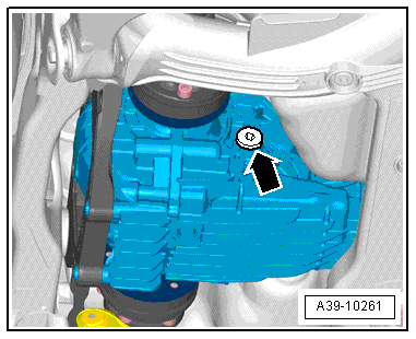
- Remove the plug to check the transmission fluid level -arrow-.
The oil level is correct when the rear final drive is filled up to the lower edge of the oil fill hole.
- Refer to the Parts Catalog for the correct transmission fluid specification.
- Install the plug -arrow- and tighten it.
Tightening specification 30 Nm.
Gear Oil, Checking Level, 0BE, 0BF
Test requirement
- Gear oil temperature: 10 ºC to 60 ºC (50º to 140 ºF)
- The rear final drive must be in the installed position.
- The vehicle must be level.
- Gear oil plug overview. Refer to → Chapter "Gear Oil Drain and Inspection Plugs Overview, 0BE, 0BF".
Special tools and workshop equipment required
- Drip Tray
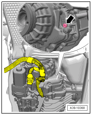
Rear Final Drive 0BF
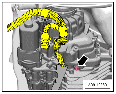
- Remove the gear oil check plug -arrow-, located on the right side of the final drive.
Rear Final Drive 0BE
- Remove the gear oil check plug -1-.
Continuation for All Rear Final Drives
- The oil level is correct when the rear final drive is filled up to the lower edge of the oil fill hole.
- Refer to the Parts Catalog for the correct transmission fluid specification.
- If necessary fill the gear oil.
- Install the gear oil inspection plug -arrow- and tighten. Tightening specification: -item 23-.
Gear Oil, Draining and Filling
Gear Oil, Draining, 0BE, 0BF
Special tools and workshop equipment required
- Drip Tray
Rear Final Drive 0BF
- Remove the gear oil check plug -arrow-.
 Note
Note
- Gear oil plug overview. Refer to → Chapter "Gear Oil Drain and Inspection Plugs Overview, 0BE, 0BF".
- Removing the gear oil check plug allows the gear oil to drain faster.
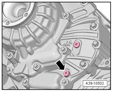
- Remove the drain plug -arrow- and drain the gear oil.
Rear Final Drive 0BE
- Remove the gear oil check plug -1-.
Note
- Gear oil plug overview. Refer to → Chapter "Gear Oil Drain and Inspection Plugs Overview, 0BE, 0BF".
- Removing the gear oil check plug allows the gear oil to drain faster.
- Remove the drain plug -arrow- and drain the gear oil.
Continuation for All Rear Final Drives
- Install the new drain plug -arrow- and tighten it. Tightening Specification -item 17-.
Gear Oil, Filling, 0BF
Special tools and workshop equipment required
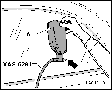
- Charging Device For Haldex Coupling 2 -VAS6291- or Charging Device For Haldex Coupling 2 -VAS6291A-
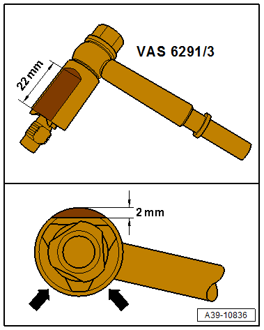
- Charging Device For Haldex Coupling 2 - Adapter 3 -VAS6291/3- (rework if necessary. Refer to → Fig. "Depending on the version the spacer tube from the Charging Device For Haldex Coupling 2 - Adapter 3 -VAS6291/3- can line up on the housing rib on the final drive.".)
- Drip Tray
Depending on the version the spacer tube from the Charging Device For Haldex Coupling 2 - Adapter 3 -VAS6291/3- can line up on the housing rib on the final drive.
- Grind the adapter spacer tube as shown, opposite the side holes -arrows-.
Gear Oil, Filling
- The rear final drive must be in the installed position.
- The vehicle must be level.
- Gear oil plug overview. Refer to → Chapter "Gear Oil Drain and Inspection Plugs Overview".
- The gear oil drain plug is installed and tightened. Tightening specification. Refer to -item 17-.
- Oil specifications. Refer to the Parts Catalog.
- Lift the vehicle.
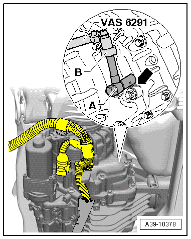
- Remove the gear oil check plug -arrow-.
- Disconnect the adapter -A- and elbow -B-.
- Install in the adapter -A- all the way.
 Caution
Risk of damaging the fluid filler hole threads.
- Do not install the adapter -A- at an angle.
- The sanded side on the adapter -A- must point to the housing rib -arrow-.
- Attach the elbow -B- to the adapter -A-.
- Route the hose over the right drive axle.
- The hose must not sag. It must be routed over the right rear wheel.
- Lower the vehicle.
- Make sure that the valve -arrow- is closed.
- Install the oil container -A- on the Charging Device For Haldex Coupling 2 -V-.
- Open the valve -arrow- and hold the oil container as shown.
The rear final drive will not be filled.
- When at the correct filling of the rear final drive oil drips between the adapter -A- and the final drive housing -arrow-.
- Lift the vehicle.
- If oil leaks from adapter -A-, set down the fluid container (for example, on a tool cart).
A portion of the excess oil runs back into the oil container.
- If no more oil runs back, remove the Charging Device For Haldex Coupling 2 -VAS6291A-.
- The oil level is correct when the rear final drive is filled up to the lower edge of the oil fill hole.
- If necessary fill the gear oil again.
- Install the new gear oil check plug -arrow- and tighten. Tightening specification. Refer to -item 23-.
