Audi A6 Typ 4G: General, Technical data
Identification
Transmission Identification
The following details can be found on the transmission housing -arrows-:
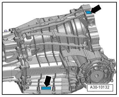
D04 = Manufacturer key
0026 = serial numberK100808 = Factory:
- K = Kassel
- 100808 = 08/10/2008
 Note
Note
- The transmission code is also listed on the vehicle data plate.
- Vehicle data label location.
Safety Precautions
Vehicle Safety Precautionsм
Observe the following to avoid personal injury and vehicle damage:
 WARNING
There is a risk of injury and accident from accidentally engaging a gear when the engine is running.
Shift the transmission into "P" and set the parking brake to lock the electro-mechanical parking brake before working on a running engine.
Danger of poisonous exhaust gas when the engine is running.
When engine is running, an exhaust extraction system must always be connected to exhaust system.
Risk of injury through fan turning on automatically.
Disconnect the connectors before working near the fan shroud.
To prevent personal injury and damage to electrical and electronic components, observe the following:
- Connect and disconnect test equipment only when the ignition is off.
 Caution
Risk of damaging electronic components when disconnecting the battery.
- Complete the steps for disconnecting the battery.
- Disconnect the battery only when the ignition is turned off, refer to → Electrical Equipment; Rep. Gr.27; Battery; Battery, Disconnecting and Connecting.
Start/Stop System Safety Precautions
Pay attention to the following when working on a vehicle with Stop/Start system:
WARNING
Danger of injury through automatic motor starting with vehicles with the Start/Stop System.
- For vehicles with an activated Start/Stop System (recognizable from a notification in the instrument cluster), the motor can be started automatically if needed.
- Make sure the Start/Stop System is disabled when working on the vehicle (turn off ignition, if needed, turn the ignition back on).
Road Test with Testing Equipment Safety Precautions
If testing equipment must be used during a road test, observe the following:
WARNING
Distraction and testing equipment that is not secured properly can cause accidents.
The passenger airbag could pose a risk if it deploys in a collision.
- Operating testing equipment while driving is a distraction.
- There is an increased risk of injury due to unsecured testing equipment.
Always secure testing equipment on the rear seat using a strap and have a second person in the rear seat operating it.
Subframe Safety Precautionsм
Note the following whenever working on the subframe:
Caution
The suspension components could be damaged.
- Do not rest the vehicle on its wheels if the subframe mount, the steering gear or the subframe crossbrace are not installed correctly.
- Do not support the vehicle on the subframe or the subframe crossbrace, for example, by a floor jack or similar device.
Towing and Tow Starting Safety Precautions
Caution
Danger of causing damage to the transmission.
When towing the vehicle, move the selector lever into "N". Do not tow the vehicle further than 50 km and do not drive faster than 50 km/h.
Note
Tow-starting the engine, for example when the battery is too weak or the starter is defective, is not possible.
Repair Informationм
Guidelines for Clean Working Conditions
- Always clean the connection locations and the area around them before loosening.
- Clean the transmission and transmission components using Cleaning Solution -D 009 401 04-.
- Use lint-free cloths when cleaning, for example, the "WYPALL X70/WORKHORSE" cloth made by Kimberly-Clark Professional.
- Seal all open lines and connections immediately with clean plugs or caps from the Engine Bung Set -VAS6122-.
- Place removed parts on a clean surface and cover them. Use foil or lint-free cloths.
- Cover or plug unpacked components if repairs cannot be performed immediately.
- Only install clean components: Remove the replacement parts from their packaging just prior to installing them.
- Protect the disconnected connectors from dirt and moisture and only connect when they are dry.
General Information
Transmission
The engine torque is transferred to the transmission via the flywheel. The transmission is built like a 7-speed manual transmission. The gear change occurs through the alternating hydraulic actuation of the two wet multi-plate clutches. The gears are automatically or manually shifted via the Tiptronic mode. Clutch pedal is not available. For more information, refer to → No.429.
Technical Data
.png)
ATF and transmission fluid (Manual Transmission Fluid)
The S tronic transmission 0B5 works with separated oil chambers for the ATF and the transmission fluid (Manual Transmission Fluid).
ATF means "Automatic Transmission Fluid".
The transmission fluid for the S tronic transmission 0B5 is also known as MTF. MTF means "Manual Transmission Fluid".
- Only the ATF available as a replacement part for the S tronic transmission 0B5 may be used for the dual clutch with hydraulics, refer to the Parts Catalog.
- Only the transmission fluid (MTF) for the S tronic transmission 0B5 that is available as a replacement part may be used for the manual transmission, the front final drive and the transfer case, refer to the Parts Catalog.
- Using other ATF or transmission fluids can result in malfunctions or transmission failure.
Shift Point Changes on Inclines and Declines
An additional gear change map automatically selects the gear changes for gradients dependent upon accelerator pedal position and driving speed.
- The gear change map for extreme uphill stretches is matched to engine output
- The gear change map for extreme downhill stretches is matched to the braking effect of the engine.
- Direct gear selection by way of the Tiptronic function permits utilization of engine braking action with a specific gear engaged, for example, on a downhill gradient with a trailer.
General Repair Information
Carefulness, cleanliness and the correct tools are required for transmission repairs to be successful. The usual basic safety precautions also, naturally apply when carrying out vehicle repairs.
Some general repair information that applies to several procedures throughout this manual is summarized here. They apply to this repair manual.
Guided Fault Finding, OBD and Test Instruments
- Before servicing the transmission, determine as best as possible the cause of the fault using the Vehicle Diagnostic Tester in Guided Fault Finding, Vehicle Self-Diagnosis and Test Instruments.
Oil, environmental and disposal regulations
- Handle ATF, transmission fluid (Manual Transmission Fluid) and other oils carefully.
- Dispose of drained ATF properly.
- Do not reuse drained ATF or transmission fluid (Manual Transmission Fluid).
- Follow the legal environmental and disposal regulations.
- Follow the information provided on oil packaging.
Special Tools and Equipment
For a complete list of special tools used in the Repair Manual refer to Workshop Equipment and Special Tools
Transmission
- Rules for cleanliness when working on the S tronic transmission, refer to → Chapter "Guidelines for Clean Working Conditions".
- Do not run engine or tow vehicle with ATF pan removed or without transmission fluid (Manual Transmission Fluid).
- Check and adjust the ATF level when replacing the transmission, refer to → Chapter "ATF Level, Checking" and check and fill the transmission fluid level, refer to → Chapter "Transmission Fluid Level, Checking". Capacities (Refer to → Chapter "Capacities"), Specifications, (Refer to the Parts Catalog).
- During installation, make sure that the alignment bushings are fitted correctly.
O-rings, shaft seals, seals
- Rules for cleanliness when working on the S tronic transmission, refer to → Chapter "Guidelines for Clean Working Conditions".
- O-rings, shaft seals and seals must be replaced.
- After removing gaskets, examine contact surface on housing/shaft for burr resulting from removal or for other signs of damage.
- Clean the housing separating surface thoroughly before assembling.
- Before installing, lightly lubricate shaft seal outer circumference and sealing lips with ATF or transmission fluid (Manual Transmission Fluid), depending on installation location.
- Coat o-rings with ATF before inserting to prevent crushing rings during installation.
- Always only use approved ATF. Other types of lubrication cause faults to occur in the transmission hydraulics.
- The open side on the shaft seals faces the fluid to be sealed off.
- Check and adjust the ATF level after installing, refer to → Chapter "ATF Level, Checking" and check and fill the transmission fluid level, refer to → Chapter "Transmission Fluid Level, Checking". Specifications, refer to the Parts Catalog.
Bolts and Nuts
- Loosen the bolts opposite the tightening sequence.
- Nuts and bolts which secure covers and housings should be tightened in steps according to the specified tightening sequence and method.
- Nuts and bolts which secure covers and housings should be loosened and tightened crosswise in stages if no tightening sequence is specified.
- Always replace self-locking nuts and bolts.
- If nothing else is specified: Use a wire brush to clean the threads of bolts that were screwed in with locking compound. Use locking fluid when installing the bolts, refer to the Parts Catalog.
- Threaded holes with self-locking bolts or bolts coated with locking fluid must be cleaned, for example using a thread tap. Otherwise there is a risk that the bolts will shear the next time they are removed.
- The tightening specifications stated apply to non-oiled nuts and bolts.
Circlips, snap rings
- Do not overstretch the circlips.
- Replace damaged or stretched circlips.
- The circlips must fit completely inside the groove.
Bearings
- Install needle bearings with lettered side (thicker metal) racing the fitting tool.
- Lubricate the bearings with transmission fluid (Manual Transmission Fluid) or with ATF, depending on the installation location.
- Do not interchange the outer or inner races for the same size bearings.
- Always replace the tapered roller bearings on one shaft together and use new bearings from a single manufacturer.
Adjusting Shims
- Measure the adjusting shims at several locations with a micrometer. Different shim thicknesses make it possible to select the required thickness precisely; install two shims if necessary.
- Check for burrs and damage. Only install perfect shims.
Mechatronic
Caution
There is a risk of destroying the transmission control module (Mechatronic) with static discharge.
- Always discharge "static electricity" before working with connectors or the Mechatronic. Do this by touching a grounded object, for example vehicle ground, the vehicle or the hoist.
- Do not touch contacts in transmission connector with hands.
Contact Corrosion
Contact corrosion can occur if unsuitable fasteners (bolts, nuts, washers, etc.) are used.
For this reason, only fasteners with a special surface coating may be installed.
In addition, rubber or plastic parts and adhesive are made of materials that do not conduct electricity.
If there are doubts about whether parts can be used or not, then use new parts, refer to the Parts Catalog.
Note:
- Only original replacement parts are recommended, they are checked and compatible with aluminum.
- It is recommended to use Audi accessories.
- Damage resulting from contact corrosion is not covered by the warranty.
Transmission Control Module Safety Functions
If one or more components and/or sensors malfunction, the automatic control module will active the appropriate replacement function. This guarantees the non-destructive operation of the transmission with respective implications on shift function and quality.
Wire Routing and Securing
- Mark the individual fuel, and vacuum lines for the EVAP canister system as well as the electrical wires before disconnecting and/or removing them. This will prevent a mix-up when reconnecting them. If necessary, draw sketches or take pictures.
- Due to the limited space inside the engine compartment, be especially careful when working near moving or hot parts to avoid damaging the lines.
Technical Data
Capacities
ATF Capacity
.png)
Caution
Danger of causing damage to the transmission.
- Only use replacement part ATF for the S tronic transmission 0B5.
- Allocation, refer to the Parts Catalog.
- Using other types of ATF can result in the malfunctions or transmission failure.
- The ATF filler tool must be clean and the ATF must not be mixed with any other oils.
- The replaceable ATF filter must also be replaced when the ATF is changed, refer to → Chapter "ATF Filter, Removing and Installing".
Transmission Fluid Capacity, MTF
The manual transmission, the manual transmission and the transfer case in the S tronic transmission 0B5 share a common transmission fluid chamber, which is checked and filled by a single plug.
Note
The transmission fluid for the S tronic transmission 0B5 is also known as MTF. MTF means "Manual Transmission Fluid".
.png)
Transmission/Engine Allocation
.png)
.png)
.png)
.png)
