Audi A6 Typ 4G: Hydraulic Control Unit, Removing and Installing
Hydraulic Control Unit, Removing and Installing, 0BE, 0BF
 Note
Note
- Pay attention to the general repair information. Refer to → Chapter "Repair Information".
- Pay attention to the safety precautions. Refer to → Chapter "Safety Precautions".
Removing
- The ignition is off.
- Place the vehicle on a lift.
- Lower the back section of the exhaust system just a little and secure it. If necessary remove the back section of the exhaust system. Refer to → Engine Mechanical, Fuel Injection and Ignition; Rep. Gr.26; Exhaust Pipes/Mufflers; Overview - Muffler.
Note
A second technician is needed to help remove the rear section of the exhaust system.
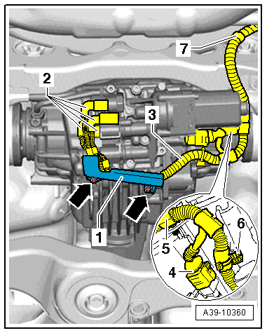
- If equipped, remove the screws -arrows- and remove the wiring harness bracket -1- from the rear final drive.
Note
Mark the Oil Pressure/Temperature Sensor and the Clutch Valves connectors -2-.
- Disconnect the connectors -2- from the Oil Pressure/Temperature Sensor and the Clutch Valves.
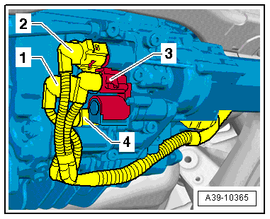
- Disconnect the connector -4- from the All Wheel Drive Pump -V415-.
- Unclip the wiring harness -3- from the final drive and the subframe and tie it up -items 5 through 7-.
- Place the Drip Tray under the rear final drive.
- Drain the ATF from the rear final drive. Refer to → Chapter "ATF, Draining and Filling".
- Drain the gear oil from the rear final drive. Refer to → Chapter "Gear Oil, Draining, 0BE, 0BF".
- Remove the All Wheel Drive Pump -V415-. Refer to → Chapter "All Wheel Drive Pump -V415-, Removing and Installing".
Note
The All Wheel Drive Pump -V415- must be removed in order to loosen and tighten the nut on the right line to the hydraulic control unit.
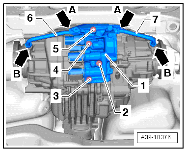
- Loosen the left -6- and right -7- lines to the hydraulic control unit -1- one turn -arrows A- and remove them from the chambers -arrows B-.
- Remove the screws -2 through 5- and remove the hydraulic control unit -1- with the seal.
Installing
Note
Follow all safety precautions exactly when replacing the hydraulic control unit. Install the "old" sensors again if possible. Refer to → Chapter "Safety Precautions and Test Procedures"
Conditions:
- Replace the seal between the hydraulic control unit -1- and the final drive housing.
- The centering pins -item 18- must be installed inside the housing for the hydraulic control unit.
- The left -6- and right -7- lines must be installed loosely when attaching the hydraulic control unit -1-.
Attach the hydraulic control unit -1- to the rear final drive as follows:
First install the lines -6 and 7- into the chambers hand-tight -arrows B-.
Then install the screws -2 through 5- hand-tight. One screw -2- has a permanent seal on the head. Coat the thread with Sealing Compound -D 176 501 A1-.
Tighten the M8 x 30 screws -2 through 5- to the tightening specification in the sequence: -4, 2, 5 and 3-.
Tighten the nuts -A arrows- and -B arrows- on the left -6- and right -7- lines to the tightening specification.
- Install the All Wheel Drive Pump -V415-. Refer to → Chapter "All Wheel Drive Pump -V415-, Removing and Installing".
- Install the wiring harness -3- to the final drive and subframe -items 5 through 7-.
- Connect the connectors -4 and 2-. Pay attention to the marks made during the removal, that identify the allocation to the Oil Pressure/Temperature Sensor and which connectors go to the Clutch Valves.
- If equipped, position the wiring harness bracket -1- on the rear final drive and tighten the bolts -arrows- to the tightening specification. Make sure the wiring harness -3- does not get pinched.
Note
- Allocation for the Oil Pressure/Temperature Sensor and Clutch Valves connectors:
- -1- = Oil Pressure/Temperature Sensor 2 -G640- Connector
- -2- = Oil Pressure/Temperature Sensor -G437- Connector
- -3- = All Wheel Drive Clutch Valve 2 -N446- Connector
- -4- = All Wheel Drive Clutch Valve -N445- Connector
- Fill the rear final drive with gear oil and then check the level. Refer to → Chapter "Gear Oil, Checking Level, 0BE, 0BF".
- Fill the ATF in the rear final drive and check the ATF level. Refer to → Chapter "ATF Level, Checking, 0BE, 0BF".
- Install the rear section of the exhaust system and align it so it is free of tension. Refer to → Rep. Gr.26; Exhaust Pipes/Mufflers; Overview - Muffler.
Hydraulic Control Unit, Disassembling and Assembling
Hydraulic Control Unit, Disassembling and Assembling, 0BE, 0BF
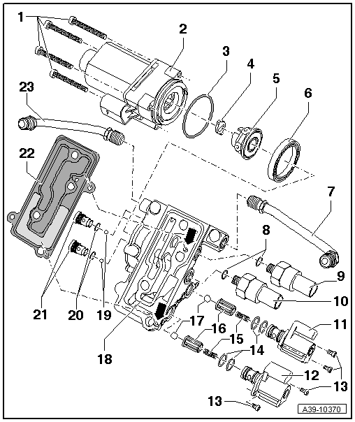
1 - Bolt
- 5 Nm
2 - All Wheel Drive Pump -V415-
- Removing and installing. Refer to → Chapter "All Wheel Drive Pump -V415-, Removing and Installing".
3 - O-Ring
- Always replace.
4 - Adapter
Note
- The adapter could fall out when removing the All Wheel Drive Pump -V415-.
- Insert the adapter into the recesses in the hydraulic pump before installing the All Wheel Drive Pump -V415-.
5 - Hydraulic Pump
- Consists of a guide ring, the housing and six pistons
- Assembling. Refer to → Fig. "Assembling the Hydraulic Pump"
6 - Ball Bearing
- Can be installed and removed by hand
7 - Left Line
- Tighten the nuts to 30 Nm.
- Is installed between the hydraulic control unit and the left chamber
- Tighten both nuts hand-tight when installing
8 - O-Ring
- Always replace.
9 - Oil Pressure/Temperature Sensor -G437-
- 10 Nm
- Brown connector
- Removing and installing. Refer to → Chapter "Oil Pressure/Temperature Sensor -G437- or Oil Pressure/Temperature Sensor 2 -G640-, Removing and Installing".
10 - Oil Pressure/Temperature Sensor 2 -G640-
- 10 Nm
- Black connector
- Removing and installing. Refer to → Chapter "Oil Pressure/Temperature Sensor -G437- or Oil Pressure/Temperature Sensor 2 -G640-, Removing and Installing".
11 - All Wheel Drive Clutch Valve 2 -N446-
- Color: brown
- Removing and installing. Refer to → Chapter "All Wheel Drive Clutch Valve -N445- or All Wheel Drive Clutch Valve 2 -N446-, Removing and Installing".
- Installed position, the connector faces upward toward the Oil Pressure/Temperature Sensor
 Caution
Do not interchange with the All Wheel Drive Clutch Valve -N445-.
12 - All Wheel Drive Clutch Valve -N445-
- Color: black
- Removing and installing. Refer to → Chapter "All Wheel Drive Clutch Valve -N445- or All Wheel Drive Clutch Valve 2 -N446-, Removing and Installing".
- Installed position, the connector faces upward toward the Oil Pressure/Temperature Sensor
Caution
Do not interchange with the All Wheel Drive Clutch Valve 2 -N446-.
13 - Bolt
- 2.5 Nm
14 - O-Ring
- Always replace.
- Mount onto the Clutch Valve
15 - Pressure Spring
- Insert into the guide -item 16-
16 - Guide
- Installation position, large diameter faced the ball -item 17-
17 - Ball
- Insert into the guide before installing -item 16-
18 - Hydraulic Control Unit Housing
- with centering pins -arrows-
- The centering pins lock the hydraulic control unit and seal to the final drive housing.
19 - Ball
- Install in the hole in the shuttle valve before installing -item 21-
20 - O-Ring
- Always replace.
21 - Shuttle Valve
- 8 Nm
- Removing and installing. Refer to → Fig. "Removing and Installing the Shuttle Valves".
22 - Seal
- With strainer
- Install on the centering pins in the hydraulic control unit housing
23 - Right Line
- Tighten the nuts to 30 Nm.
- Is installed between the hydraulic control unit and the right chamber
- Tighten both nuts hand-tight when installing
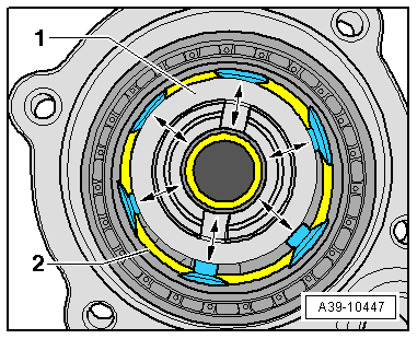
Assembling the Hydraulic Pump
- Install the six pistons -A- in the housing -B-.
- Install the guiding ring -C- so that the piston touches the collar -arrow-.
- Insert the hydraulic pump -1- with the guide ring -2- in the in the hydraulic control unit housing.
Function Test:
- Turn the hydraulic pump -1- several times. While doing so pay attention to the following:
- When turning the hydraulic pump must not become hooked or tilted.
- All pistons must be removed and pressed in.
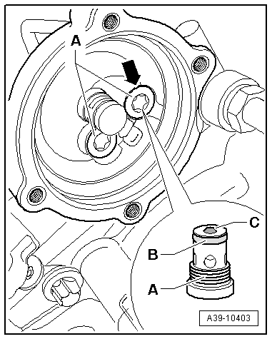
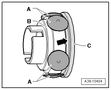
Removing and Installing the Shuttle Valves
Note
Remove the All Wheel Drive Pump -V415-, hydraulic pump and ball bearing -item 6- beforehand.
- Remove the shuttle valves -A-. Always remove the ball -C- as well.
- Insert the ball into the hole in the shuttle valve when installing.
- Install the shuttle valve all the way with a new O-ring -B-.
- The shuttle valve must rest lower than the opposing housing surface -arrow-. If this is not the case, then the remove the valve again and adjust the position of the ball.
- Tighten the shuttle valve to the tightening specification -item 21-