Audi A6 Typ 4G: Hydraulic System
General Information, Brake Fluid
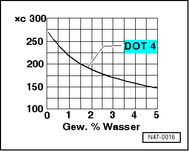
Brake fluid is hygroscopic, meaning that it has the ability to absorb water and moisture from the air.
If water has been absorbed, the boiling point will drop, for example, during high braking temperatures the brake fluid may develop steam bubbles and cause the brakes to fail.
Over time, brake fluid will darken in color. Dark-colored brake fluid does not indicate anything about its quality. The color forms due to chemical reactions.
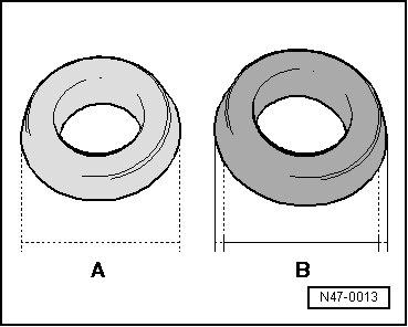
Even the smallest amount on a seal or boot can cause the part to change and thereby affect the function of the brake system. The results of an unclean brake system first show themselves months later, causing increased repair costs, especially on vehicles with ABS.
A = Boot - Original size
B = Boot - Swollen through contact with mineral oil
As a result of the previously mentioned points:
- Keep brake fluid containers tightly and securely sealed. Only this can ensure that no oil, dirt or cleaning materials and no humidity can enter the container.
- Store brake fluid containers away from oil (even hydraulic oil) and cleaning fluids to prevent an accidental mixing of both fluids or even filling the brake system with the wrong fluid.
 WARNING
Health risks!
- Brake fluid is poisonous, and must never be siphoned by mouth under any circumstances.
- To prevent skin contact with brake fluid, wear chemical resistant safety gloves.
- Follow all disposal regulations.
There is a risk of an accident from steam bubbles developing when the water content in the brake fluid is too high.
- Brake fluid is hygroscopic, meaning that it absorbs moisture from the surrounding air.
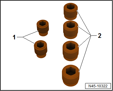
- Seal the open brake hoses and brake line with plugs from the Assembly Part Set -5Q0698311-.
- Always store brake fluid in air-tight containers.
Brake fluid contact with fluids containing mineral oils causes malfunctions.
Brake fluid must never come into contact with fluids containing mineral oils (oil, gas, cleaning solutions). Safety gloves must be free of oil and grease.
Risk of damaging the painted surfaces.
Due to its corrosive nature, brake fluid must also never contact paint. Wash off any spilled brake fluid immediately with plenty of water.
 Note
Note
- Use new brake fluid only.
- Rinse any spilled brake fluid with plenty of water.
Hydraulic System, Standard Bleeding
Hydraulic System, Standard Bleeding with Brake Charger/Bleeding Unit
Special tools and workshop equipment required
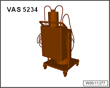
- Brake Charger/Bleeder Unit -VAS5234- with Brake Bleeder Adapter -VAS5234/1-
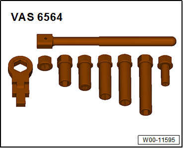
- Brake Bleeding Tool Set -VAS6564-
- Container
Procedure
Note
Make sure that the brake fluid reservoir is always filled.
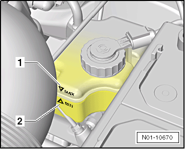
- Fill the brake fluid reservoir up to the "MAX" mark.
- Connect the Brake Charger/Bleeder Unit -VAS5234- with Brake Bleeder Adapter -VAS5234/1-.
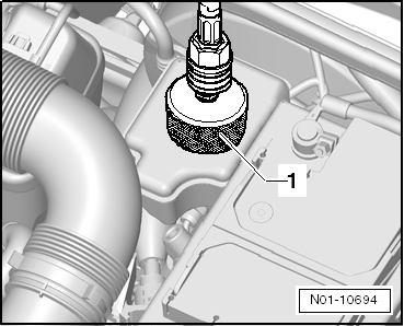
- Attach the adapter -1- to the brake fluid reservoir.
- Adjust the pressure direction on the Brake Charger/Bleeder Unit -VAS5234-. Refer to the Owner's Manual for the Brake Charger/Bleeder Unit -VAS5234-.
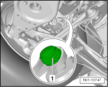
- Remove the left and right front dust caps -1-.
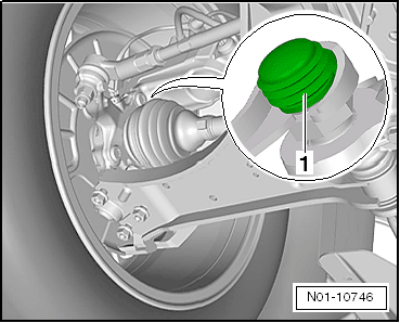
- Remove the left and right rear dust caps -1-.
Note
Use a suitable bleeder hose. It must be seated tightly on the bleed screw so that no air can enter the brake system.
- Attach the bleed hose from the reservoir to the bleed screw.
Bleeding sequence
1 - Left Front Brake Caliper
2 - Right Front Brake Caliper
3 - Left Rear Brake Caliper
4 - Right Rear Brake Caliper
- Leave the bleed screw open, with container hose connected, until brake fluid flows out clear and free of air bubbles.
- Press brake pedal five times to assist the bleeding procedure.
- Tighten the bleed screw, remove the bleeder hose and place the dust cap on the bleed screw.
- Repeat the bleeding procedure in the specified sequence for the remaining brake calipers.
- Fill the brake fluid reservoir under consideration of brake pad wear up to the "MAX" mark and screw on the fuel cap.
Note
Do not add more brake fluid above the "MAX" mark -1- otherwise it will leak out of the reservoir.
- Start the engine and check the brake pedal travel and pressure.
- If the pedal travel is too long, check the brake system for leaks or repeat the bleeding procedure.
Note
A road test must be performed after bleeding. During this, at least one ABS regulation must be performed at all four wheels!
Changing the brake fluid
WARNING
Risk of accident!
Make sure the brakes are working correctly before driving the vehicle for the first time.
Brake System, Bleeding without Brake Charger/Bleeding Unit
Special tools and workshop equipment required
- Brake Bleeding Tool Set -VAS6564-
- Container
Procedure
Note
Make sure that the brake fluid reservoir is always filled.
- Fill the brake fluid reservoir up to the "MAX" mark.
- Remove the left and right front dust caps -1-.
- Remove the left and right rear dust caps -1-.
Note
Use a suitable bleeder hose. It must be seated tightly on the bleed screw so that no air can enter the brake system.
- Attach the bleed hose from the reservoir to the bleed screw.
Bleeding sequence
1 - Left Front Brake Caliper
2 - Right Front Brake Caliper
3 - Left Rear Brake Caliper
4 - Right Rear Brake Caliper
- Build pressure up in brake system by pumping brake pedal.
Note
Slowly depress the brake pedal to prevent the formation of bubbles.
- As soon as pressure is built up, hold brake pedal in depressed position.
- Leave the bleed screw open, with container hose connected, until brake fluid flows out clear and free of air bubbles.
- Hold pedal in completely depressed position and close the bleed screw.
- Release brake pedal and wait approximately two seconds so that brake fluid can flow out of the brake fluid reservoir.
- Repeat the procedure until the brake fluid flows out clear and without bubbles.
- Tighten the bleed screw, remove the bleeder hose and place the protective cap on the bleed screw.
- Repeat the bleeding procedure in the specified sequence for the remaining brake calipers.
- Fill the brake fluid reservoir under consideration of brake pad wear up to the "MAX" mark and screw on the fuel cap.
Note
Do not add more brake fluid above the "MAX" mark -1- otherwise it will leak out of the reservoir.
- Start the engine and check the brake pedal travel and pressure.
- If the pedal travel is too long, check the brake system for leaks or repeat the bleeding procedure.
Changing the brake fluid
WARNING
Risk of accident!
Make sure the brakes are working correctly before driving the vehicle for the first time.
Leak Test
Special tools and workshop equipment required
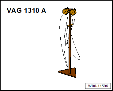
- Brake Pressure Gauge -VAG1310A-
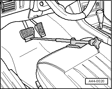
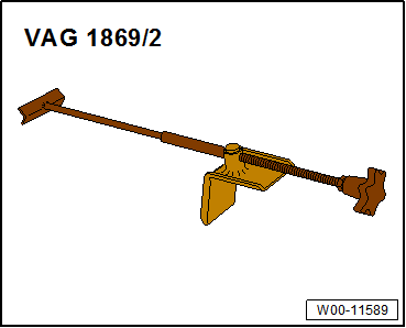
- Brake Pedal Actuator -VAG1869/2-.
High pressure test:
- Brake system (brake master cylinder, brake hoses, brake lines and brake calipers) tested for function and leaks.
- Remove the bleed screw at one of the front brake calipers. Connect the Brake Pressure Gauge -VAG1310A- and bleed.
- Insert the Brake Pedal Actuator -VAG1869/2- between the brake pedal and driver seat. Apply pressure to the brake pedal until the pressure gauge indicates a pressure of 50 bar. The pressure must not drop more than 4 bar during the test period of 45 seconds.
Replace the brake master cylinder if the pressure decrease is too high.
Low pressure testing:
- Set the brake pedal actuator back far enough that the pressure gauge indicates 6 bar positive pressure.
- The pressure must not drop by more than 1 bar during a test period of 3 minutes.
Replace the brake master cylinder if the pressure decrease is too high.
Special Tools
Special tools and workshop equipment required
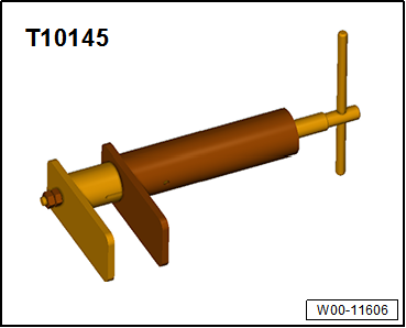
- Piston Resetting Tool -T10145-
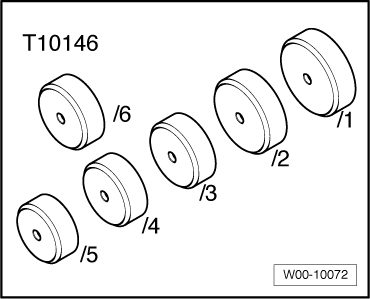
- Piston Resetting Tool - Cap 5 -T10146/5- from Piston Resetting Tool - Caps /1,/2,/3,/4,/5 -T10146-
- Brake Pressure Gauge -VAG1310A-
- Torque Wrench 1331 5-50Nm -VAG1331-
- Brake Pedal Actuator -VAG1869/2-.
- Brake Charger/Bleeder Unit -VAS5234-
- Brake Bleeder Adapter -VAS5234/1-
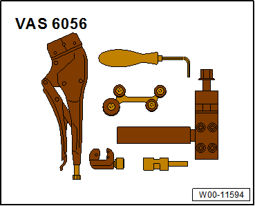
- Brake Line Tool Kit -VAS6056-
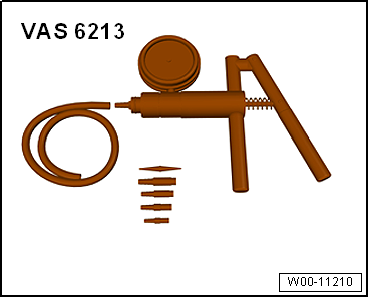
- Hand Vacuum Pump -VAS6213-
- Brake Bleeding Tool Set -VAS6564-
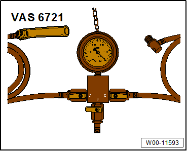
- Brake Servo Tester -VAS6721-
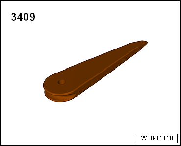
- Trim Removal Wedge -3409-
- M10 Plugs -1- and M12 Plugs -2-Assembly Part Set -5Q0698311-
Revision History
DRUCK NUMBER: A005A701121