Audi A6 Typ 4G: Steering Gear, Removing and Installing
 Note
Note
Power steering gear is completely removed and installed with tie rods.
A removable heat shield mat was installed on the steering gear at start of production. Be sure to install this mat if installing the old steering gear again.
A removable heat shield mat on the steering gear was replaced by a bonded heat shield mat as a running change. It is therefore not necessary to take the mat from the old steering gear and installing on a new steering gear.
A replacement steering gear comes with the bonded heat shield mat.
Special tools and workshop equipment required
- Torque Wrench 1331 5-50Nm -VAG1331-
- Torque Wrench 1332 40-200Nm -VAG1332-
- Torque Wrench 1332 Insert - Ring Wrench - 21mm -VAG1332/7-
- Puller - Ball Joint -T40010A-
Removing
- Straighten the wheels.
- Turn off the ignition and remove the key.
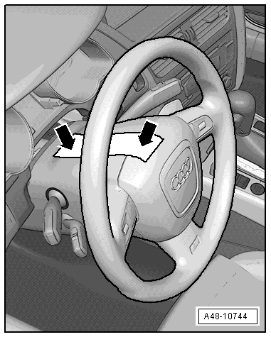
- Turn the steering wheel so that the wheels are in the straight-ahead position and then tape it secure -arrow- so that it cannot turn.
Note
- Be sure to use tape that will not leave behind any residue when it is removed.
- Be careful not to turn the steering wheel during the repair because the Airbag Spiral Spring/Return Spring with Slip Ring -F138- can become damaged.
- Remove the front wheels. Refer to → Chapter "Wheels and Tires".
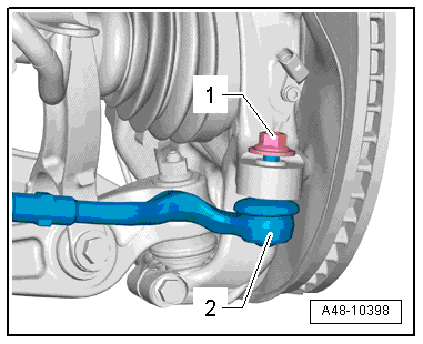
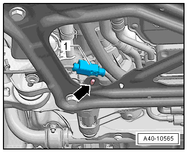
- Remove the nut -1- from the tie rod end joint pin -2- until it is flush with the joint pin threads. Counterhold when loosening.
Note
To protect thread, screw nut on pin a few turns.
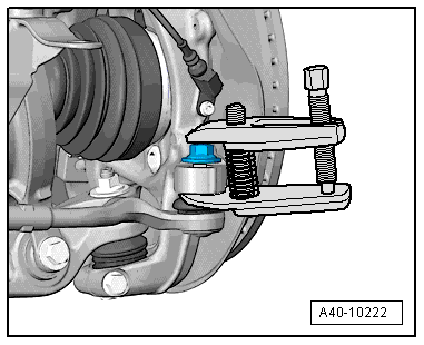
- Remove the tie rod end from the wheel bearing housing using the Puller - Ball Joint -T40010A-. Remove the nut.
Note
Make sure that both puller lever arms are parallel to each other when using greatest force, adjust if necessary.
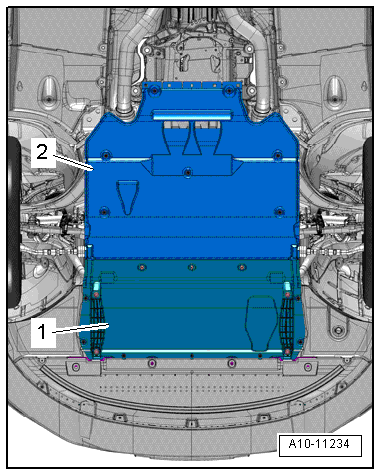
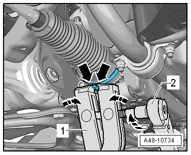
- Remove the noise insulations -1 and 2-. Refer to → Body Exterior; Rep. Gr.66; Noise Insulation; Noise Insulation, Removing and Installing.
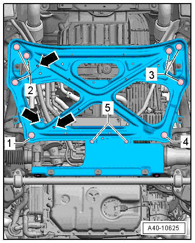
- Remove the nuts -arrows- and the stabilizer bar.
- Free up the clip -arrow-, disconnect the connector -1- and free up the electric wire.
- Remove the remaining clips -arrows- on the crossbrace and free up the wiring harness.
- Remove the crossbrace. Refer to → Chapter "Subframe Crossbrace, Removing and Installing".
 Caution
The suspension components could be damaged.
- If the subframe mount, the steering gear or the subframe crossbrace are not installed correctly, do not rest the vehicle on its wheels.
- The vehicle must not be supported on the subframe or the subframe crossbrace (for example using a floor jack).
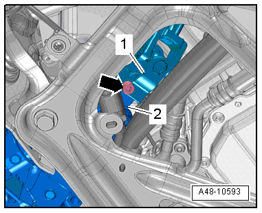
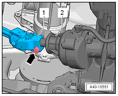
- Remove the bolt -arrow-.
- Remove the steering intermediate shaft -1- from the steering gear -2- and support the steering intermediate shaft so that it cannot slide out.
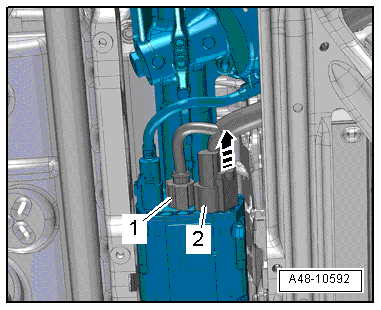
- Release the safety mechanism and push the retainer downward and remove the connector -1- for the vehicle signals (CAN bus and terminal 15) from the Power Steering Control Module -J500-.
- Release the safety mechanism -arrow-, push the retainer downward and disconnect the connector -2- for the voltage (terminal 30) from the Power Steering Control Module -J500-.
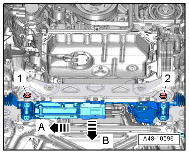
- Remove the bolts -1 and 2-.
- Push the steering gear slightly to the side -arrow A- and remove it downward -arrow B-.
Installing
Install in reverse order of removal. Note the following:
- Install both bolts -1 and 2- loosely at first and then tighten them.
 WARNING
Pull on the steering intermediate shaft -1- to make sure it is secure when the bolt -arrow- is installed. Then tighten the bolt -arrow-.
- Install the stabilizer bar. Refer to → Chapter "Stabilizer Bar, Removing and Installing".
- Install the crossbrace. Refer to → Chapter "Subframe Crossbrace, Removing and Installing".
The "program"J500 Replace Control Module must be started in Guided Fault Finding on the Vehicle Diagnostic Tester if new electromechanical steering gear is installed.
- Perform an axle alignment. Refer to → Chapter "Vehicle Alignment".
Boot, Removing and Installing
Special tools and workshop equipment required
- Torque Wrench 1331 5-50Nm -VAG1331-
- Torque Wrench 1332 40-200Nm -VAG1332-
- Torque Wrench 1332 Insert - Ring Wrench - 21mm -VAG1332/7-
- Hose Clip Pliers -VAG1921-
- Clamping Pliers -VAG1682A- with Clamping Pliers - Jaws -VAG1682A/1-
- Puller - Ball Joint -T40010A-
Removing
Replace the boot each time it is removed.
Caution
If the boot is faulty, moisture and dirt will penetrate into steering gear. There must be a noticeable grease film present on steering rack in area of splines. If grease film is not present, steering gear must be replaced. Steering gear must also be replaced if there is corrosion or steering gear is damaged or worn out.
- Remove the front wheel. Refer to → Chapter "Wheels and Tires".
- Straighten the wheels.
- Remove the noise insulation. Refer to → Body Exterior; Rep. Gr.66; Noise Insulation; Noise Insulation, Removing and Installing.
- Clean the power steering gear and subframe in the boot area.
Caution
While doing this, no dirt must enter the steering gear through the faulty boot.
- Remove the nut -1- from the tie rod end joint pin -2- until it is flush with the joint pin threads. Counterhold when loosening.
To Protect Thread, Screw Nut on Pin A Few Turns.
- Remove the tie rod end from the wheel bearing housing using the Puller - Ball Joint -T40010A-. Remove the nut.
Note
Make sure that both puller lever arms are parallel to each other when using greatest force, adjust if necessary.
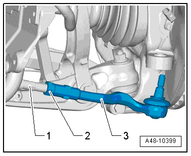
- Mark the installed position of the nut -2- on the tie rod -1- for later.
- Counterhold the tie rod end -3- and loosen the nut -2-.
- Open the spring clamp -3- with the Hose Clip Pliers -VAG1921- and remove it.
- Remove the clamp -1- and remove the boot -2- from the power steering gear.
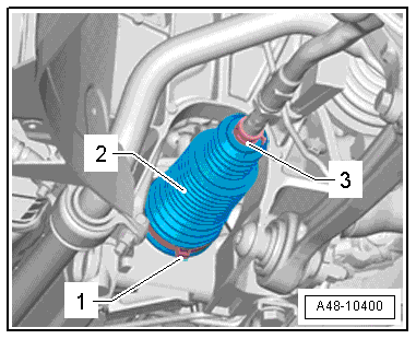
- Remove the tie rod end -3- and nut -2- from the tie rod -1-.
- Pull off the boot with spring clamp from tie rod.
Note
- If corrosion, damage, wear-out or first signs of soiling on steering rack can be seen, complete steering gear must be replaced.
- If no grease film is visible on steering rack, steering gear must also be replaced completely.
Installing
Install in reverse order of removal. Note the following:
Replace the boot each time it is removed.
Coat the inside of the joint boot seat all the way around and evenly with Power Steering Gear Grease before installing. Refer to the Parts Catalog.
Check the seat for the boot on the steering gear for damage before installing. If the steering gear housing is damaged, replace the steering gear.
Before installing, coat the steering rack with the grease supplied in the repair set.
Caution
Do not use other grease under any circumstances.
For this purpose, turn steering to stop toward both sides in succession.
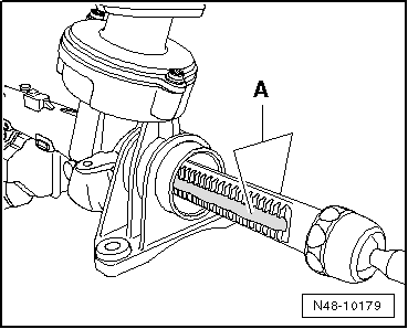
For clearer illustration, steering gear has been removed in the illustration.
- Grease the steering rack on the toothed side -A- and on the thrust piece side with grease.
Note
To grease the rack, only use power steering gear grease. Note: there are different types of grease for the left and right. For allocation. Refer to the Parts Catalog.
- Straighten the wheels.
- Guide new clamp and boot onto tie rod.
- Install the nut -1- and tie rod -3- up to the marking applied during removal.
- Tighten the nut -2- to the specification. Counterhold the tie rod end -3-. Slide the boot onto the steering gear housing with a new clamp.
- Make sure the boot is seated correctly on the power steering gear.
- The boot must fit in the groove and on the contour of the power steering gear.
Inner Clamp Assembly
- Install the Tension Rod as shown in the illustration. Make sure that the jaws of the clamp tool are seated in the corners -arrows- of the clamp.
- Tighten the clamp by turning the spindle using a torque wrench (do not tilt the pliers).
- Tightening specification.
- Use torque wrench with 5 to 50 Nm range (for example, Torque Wrench 1331 5-50Nm -VAG1331-).
- Make sure the thread on the spindle -1- is easy to move. Lubricate with MoS2 grease, if necessary.
- If the thread is tight, for example, dirty, the required tensioning force for the hose clamp will not be achieved in spite of correct torque specification settings.
- Secure the spring clamp -3- on the boot -2- using the Hose Clip Pliers -VAG1921-.
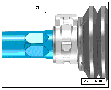
Outer Boot Assembly
- Dimension -a- = 2 mm.
Install in reverse order of removal.
- To determine if an axle alignment is required, see Table. Refer to → Chapter "Evaluating Need for Axle Alignment".
The axle alignment must be performed on a VW/Audi approved alignment stand.