Audi A6 Typ 4G: Information Electronics Control Module 1 -J794-, Removing and Installing
Information Electronics Control Module 1 -J794-, Removing and Installing
Special tools and workshop equipment required
- Fiber-Optic Repair Set - Connector Protective Caps -VAS 6223/9-.
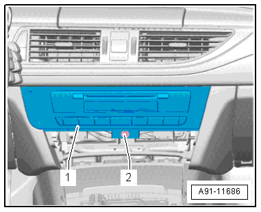
The Information Electronics Control Module 1 -J794- is located inside the instrument panel.
 Note
Note
If replacing the control module, select the "Replace Control Module" function on the Vehicle Diagnostic Tester.
Removing
- Remove any CDs still in the Information Electronics Control Module 1 -J794-.
- Turn off the ignition and all electrical consumers and remove the ignition key.
- Remove the Climatronic Control Module -J255-. Refer to → Heating, Ventilation, and Air Conditioning; Rep. Gr.87; Display and Control Head; Display and Control Head, Removing and Installing.
- Remove the screw -2- on the Information Electronics Control Module 1 -J794--1-.
- Remove the Information Electronics Control Module 1 -J794--1- from the mounting frame.
 Caution
Pay attention to the wire routing to the display in the instrument panel. It will not be possible to extend the display again if the wiring is routed incorrectly during installation.
- Release and disconnect all connectors from the Information Electronics Control Module 1 -J794- and from the trim with switches.
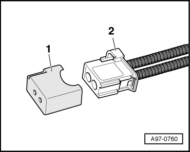
- Insert the Fiber-Optic Repair Set - Connector Protective Caps -VAS6223/9--1- onto the MOST Bus connector -2-.
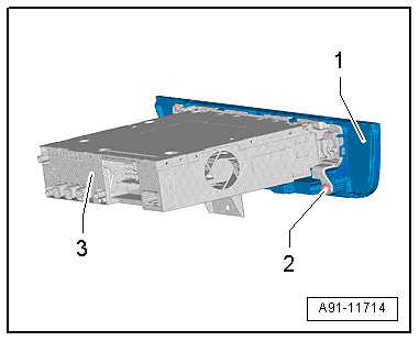
Next, the trim with the switches -1- must be removed from the Information Electronics Control Module 1 -J794--3-.
Removing the trim
- Remove the four screws -2- and remove the trim with switches -1- from the Information Electronics Control Module 1 -J794--3-.
Installing
- Install in reverse order of removal.
- Make sure that the wiring guide of the Front Information Display Control Head -J685- to the wiring harness and Information Electronics Control Module 1 -J794- is followed exactly, otherwise the Front Information Display Control Head -J685- will not extend out.
Caution
Pay attention to the wire routing to the display in the instrument panel. It will not be possible to extend the display again if the wiring is routed incorrectly during installation.
Information Electronics Control Module 2 -J829-, Removing and Installing
Special tools and workshop equipment required
- Radio Removal Tool -T10057-
- Fiber-Optic Repair Set - Connector Protective Caps -VAS6223/9-.
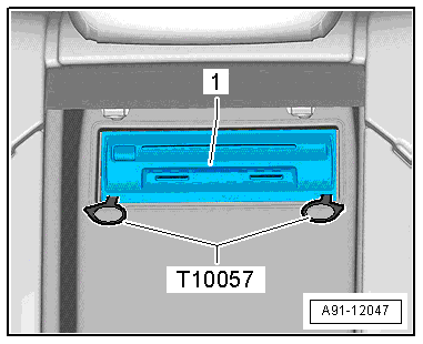
The Information Electronics Control Module 2 -J829--1- is located between the rear seats inside the rear panel.
Note
If replacing the control module, select the "Replace Control Module" function on the Vehicle Diagnostic Tester.
Removing
- Fold the center armrest down and back.
- Remove any DVD or SD card remaining in the Information Electronics Control Module 2 -J829-.
- Turn off the ignition and all electrical consumers and remove the ignition key.
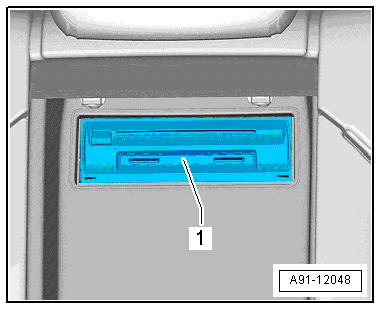
- Insert the two clips from the Radio Removal Tool -T10057- into the slits in the Information Electronics Control Module 2 -J829--1- until they lock into place. Points on the grip eyelets of tool face outward.
- Remove the Information Electronics Control Module 2 -J829--1- from the mounting frame.
- Press the release tabs on the Information Electronics Control Module 2 -J829- and remove the Radio Removal Tool -T10057-.
- Release and disconnect the connectors from the Information Electronics Control Module 2 -J829-.
- Insert the Fiber-Optic Repair Set - Connector Protective Caps -VAS6223/9--1- onto the MOST Bus connector -2-.
Installing
- Connect all the connectors.
- Insert Information Electronics Control Module 2 -J829- into the frame until it locks into place.
